
soldano slo preamp

The described circuit involves a triode amplifier stage characterized by its output impedance, load configuration, and feedback mechanism. The AC load consists of resistive components that define the operating conditions for audio signals, particularly in the context of overdrive performance. The use of the 2.2M and 330k resistors in parallel establishes a specific load that impacts the gain and frequency response of the circuit. The output impedance of 74k, combined with the capacitive element, introduces frequency-dependent behavior that influences the amplifier's performance across the audio spectrum.
The triode's biasing is crucial, with the grid voltage determining the operating point and the resulting current through the cathode resistor. The presence of the 39k cathode resistor is significant, as it provides negative feedback that stabilizes the circuit against variations in input signal amplitude. This feedback mechanism is essential for maintaining linearity and controlling distortion levels, particularly as the triode approaches cutoff.
The inclusion of the plate bypass capacitor serves to manage high-frequency response, preventing unwanted oscillations while simultaneously shaping the frequency response. The capacitor's value is carefully chosen to balance treble attenuation with bass gain, allowing the amplifier to maintain a desirable tonal character.
As the circuit operates, the relationship between grid voltage and plate current becomes evident, with specific swings in voltage and current dictating the overall gain and headroom available for signal processing. The design considerations taken into account, such as the effective load seen by the output stage and the resulting cutoff frequency, contribute to the overall dynamic range and tonal quality of the amplifier.
The transition into overdrive is a critical aspect of the amplifier's design, with the characteristics of the output signal being influenced by the operating conditions and feedback mechanisms in place. The potential for harmonic distortion, particularly second harmonic distortion, is a direct result of the amplifier's biasing and feedback strategies, ultimately shaping the musicality and expressiveness of the circuit. Adjustments to the DC operating point can further refine the performance, allowing for a more balanced response across varying signal levels.The AC load consists of a 2. 2M resistor in parallel with a 330k resistor and the output impedance Zo of the normal channel`s second stage. Here is what that stage looks like: For audio frequencies its output impedance is 74k plus the impedance of 120pF in parallel with 2.
2M. If we ignore the small capacitor, then the overdrive channel`s load for m idrange signals is equal to As the grid voltage varies from minus 3. 5 to minus 4. 5 volts the current passing through the 38k cathode resistor rises from 0. 09mA to 1. 1mA, as shown by the green grid line shown below. The triode is thus biased very close to cutoff at a grid voltage of about minus 4 volts. Such a situation may seem a bit perilous, but having a whopping 39k at the cathode creates substantial negative feedback to counteract changes in grid voltage due to the input signal. We`ll take a look at why this stage is not as close to cutoff as it appears and then examine the distortion effects of operating in this region of the curves.
This stage has a 0. 001uF plate bypass capacitor to prevent high-frequency parasitic oscillation. It serves the same purpose, for example, as the 47pF capacitor between the plates of the Fender Bassman`s long tailed pair. In this case, however, the value is much higher, creating significant treble attenuation. At high treble frequencies the 0. 001uF plate bypass capacitor acts as a short circuit and gain is zero. At bass frequencies the capacitor is open and there is an effective gain of about 1. 8 (5dB), providing significant bass boost but not a lot of voltage gain compared to upstream stages. For audio signals the capacitor is in parallel with an output impedance of 98k and an effective load of 255k (as described earlier).
This creates a -3dB treble cutoff frequency of 2. 2kHz. Potential gain is dramatically reduced by the large, unbypassed cathode resistor which creates substantial negative feedback. This makes the cathode "follow" the grid. (This is not a cathode follower, however, because the output is taken from the plate, not the cathode.
) Thus the grid-to-cathode voltage, which is the value shown in the characteristic curves below, is much less than the grid-to-ground voltage, which represents the input signal. This means that a drop in plate voltage from 335 volts (the DC value) to zero volts creates an increase in current of 335 / 111k = 3mA.
The current thus rises from 0. 1mA (the DC value) to 3. 1mA, which forms the upper left end of the blue AC load line show here. A grid voltage swing of about plus or minus 0. 3 volts relative to the DC operating point of minus 4 volts is all that can be achieved without the tube going into cutoff. The corresponding plate current swing is plus or minus 0. 1mA, which creates a voltage swing across the cathode resistor of plus or minus (0. 1mA)(39k) = 3. 9 volts. Thus the signal needed at the input is plus or minus 3. 9 + 0. 3 = 4. 2 volts. There is thus more headroom in this stage than in previous stages, despite a DC operating point barely above cutoff.
Using 34 for the gain of the first stage, 60 for the gain of the second stage, and 0. 68 for the gain of the second stage output circuit, the signal at the input jack required to overdrive the third stage is This is very easily achieved. Even with low-gain pickups, when the volume controls are at maximum it takes very little pick pressure to force the third stage well into overdrive.
Under typical volume control settings this stage transitions into overdrive long before the previous stages. Operating this stage close to cutoff and far from saturation affects harmonic distortion and the dynamics of how rapidly the circuit transitions into overdrive.
Because negative signal swings are flattened long before positive swings, the output signal shape is unsymmetrical, creating primarily second harmonic distortion. Placing the DC operating point closer to the center of the load line would c 🔗 External reference
Related Circuits
The schematic in question pertains to a phono preamplifier that is characterized by an accurate RIAA equalisation curve. Notably, this preamplifier boasts superior sonic performance compared to most others featured in magazines and application notes. This preamplifier, much like other...
In recent years, following CD's introduction, vinyl recordings are almost disappeared. Nevertheless, a phono preamplifier is still useful for listening to old vinyl discs from a well-preserved collection. This simple but efficient circuit devised for cheap moving-magnet cartridges can be...
This design adopts a well established circuit topology for the power amplifier, using a single-rail supply of about 60V and capacitor-coupling for the speaker(s). The advantages for a guitar amplifier are the very simple circuitry, even for comparatively high...
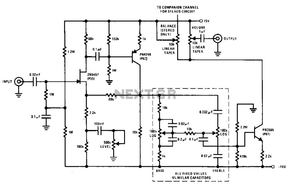
This preamplifier and tone control circuit utilizes a JFET to maximize its performance as a low-noise, high-input impedance device. All device parameters are non-critical, yet the circuit achieves harmonic distortion levels below 0.05% with a signal-to-noise ratio exceeding 85...
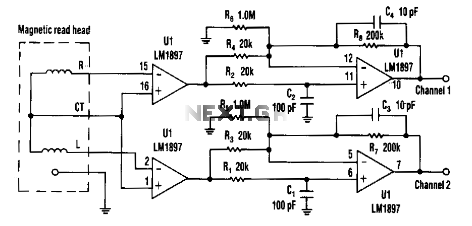
Choosing direct current (DC) coupling instead of alternating current (AC) coupling can significantly reduce the noise associated with preamplifiers for a magnetic reading head, particularly at low frequencies. The LM1897 eliminates the need for the capacitor that typically AC...
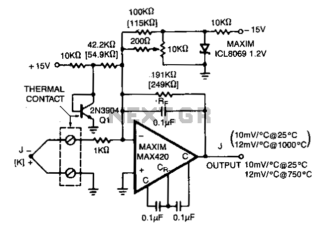
The MAX420 is operated at a gain of 191 to convert the 52 µV/°C output of the type J thermocouple to a 10 mV/°C signal. The -2.2 mV/°C temperature coefficient of the 2N3904 is added into the summing junction...