
Sound Level Meter

The sound level meter utilizes the LM3915, a versatile LED bar graph or LED dot display driver, which is designed to provide a visual representation of audio levels. The IC operates on a wide voltage range, typically between 3V and 25V, making it suitable for various applications. The configuration allows for either a bar graph or a dot mode display, depending on the external connections made to the IC.
To implement this circuit, a few essential external components are needed. These typically include resistors to set the reference voltage for the IC, capacitors for filtering and stability, and LEDs for visual output. The LM3915 can drive up to ten LEDs directly, providing a clear and straightforward indication of sound levels.
The circuit can be powered by a simple battery or a regulated power supply, depending on the intended application. The input signal can be taken from a microphone or any audio source, which is then processed by the LM3915 to generate the corresponding visual output. An optional preamplifier stage may be added to enhance the performance, especially in low-level audio applications.
Overall, this sound level meter circuit is an efficient solution for monitoring audio levels in various environments, such as sound engineering, broadcasting, or personal audio systems. Its solid-state design ensures reliability, while the simplicity of the circuit promotes ease of use and integration into existing systems.This nifty sound level meter is a perfect one chip replacement for the standard analog meters. It is completely solid state and will never wear out. The whole circuit is based on the LM3915 audio level IC and uses only a few external components. 🔗 External reference
Related Circuits
The circuit presented is designed to prevent burning one's tongue by monitoring the temperature of coffee. It consists of a voltage regulator, a temperature-to-voltage converter, a comparator, and two LEDs. In general, the circuit operates as follows: if the...

This design circuit is for converting voltage to frequency. Typically, frequency meters are used in speed sensors, tachometers, and for measuring recurring signals. The frequency to voltage converter (FVC) can transform voltage into either a digital or analog tachometer....

The circuit utilizes the Trigger and Threshold pins (2 and 6) to monitor maximum and minimum voltage levels. Two voltage comparator operational amplifiers within the 555 timer manage the output state, switching it on or off. The Trigger pin...

Easy to build homemade 50 MHz (6-meter band) vertical half-wave antenna. Omnidirectional, high gain, low SWR. The proposed design for a 50 MHz vertical half-wave antenna is intended for amateur radio applications, specifically within the 6-meter band. This antenna configuration...
Any ideas? Is this circuit going to be standalone? Is there any other circuitry around it, perhaps a microcontroller? What circuitry does the timing device contain, or does it even contain electronics? Abdullah Kahraman Mar 22, '13 at 18:10....
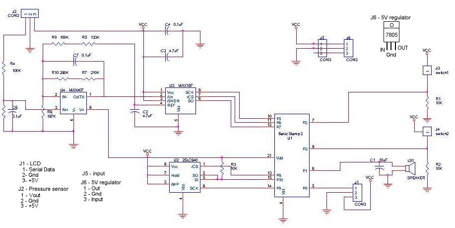
A method for determining altitude involves the use of barometric pressure; however, it presents certain challenges. The relationship between pressure and altitude is not linear but rather complex, a concept developed by the army in the 1930s. The equation...