
sound source locator uses

This circuit serves as a sound localization tool, effectively amplifying and processing audio signals from various sources. The electret microphone captures sound waves, converting them into electrical signals, which are then amplified by the PreChamp preamplifier. The design allows for adjustable gain settings, enabling the user to tailor the sensitivity of the circuit to the specific environment and sound source.
The two-transistor configuration of the PreChamp preamplifier enhances the signal-to-noise ratio, making it suitable for detecting faint sounds amidst background noise. The biasing of Q1 ensures that the transistor operates in a region where it can effectively respond to the amplified signals from the microphone. The interaction between the microphone, preamplifier, and analog meter provides a visual representation of sound intensity, allowing users to pinpoint the location of the sound source.
The integration of the trimpot VR1 facilitates calibration of the device, ensuring accurate readings on the analog meter. The quick discharge capability provided by switch S2 is particularly useful for field applications where rapid measurements may be required. Overall, this circuit exemplifies a practical approach to sound detection and localization, making it a valuable tool for various applications, including maintenance checks for machinery and safety inspections for gas leaks.This circuit could be regarded as a simple alternative to the Sooper Snooper device featured elsewhere in this issue. It is based on the PreChamp preamplifier featured in the July 1994 issue of SILICON CHIP. It can be used to pinpoint or locate sounds coming from inconspicuous sources such as a noisy bearing in a VCR containing many bearings.
Othe r examples are an audible gas leak or a puncture in a slowly deflating tyre, provided the background noise level is considerably less than the source noise. The device uses an electret microphone. This is attached to the end of round Texta casing of the same diameter, then covered with spaghetti sleeving and overlapping the electret by 5mm to make it more directional.
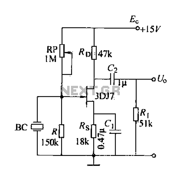
The electret was then wired to the two-transistor Pre-Champ preamplifier (available from Dick Smith Electronics, Jaycar & Altronics as a kit). The 2. 2k © feedback resistor in the preamplifier is replaced with switch S1 and four resistors 2. 2k ©, 4. 7k ©, 10k © and 22k © to give gains of 23, 48, 101 and 221, respectively. After passing through the modified PreChamp, the signal goes to the base of Q1 which is biased on the verge of turning on by the 100k © and 6.
8k © resistors. When the electret microphone picks up a sound, the amplified signal is fed to the base of Q1 turning it on and drawing current via diode D1 to reduce the stored charge in C1, the 220 F electrolytic capacitor. This results in a dip in the reading of analog meter M1. Meanwhile C1 is constantly being charged via the 10k © resistor and the 50k © trimpot VR1. VR1 is set to provide full scale deflection on meter M1 when no signal is present. If a 50uA meter movement is used it will required a suitable shunt resistor to suit the circuit. Summing up, as the unit is used to home in on a sound source, louder sounds cause the meter reading to drop.
Frequencies below 20Hz will cause the meter pointer to flutter. Switch S2 and the associated 1k © resistor are provided to quickly discharge C1 to enable repeated measurements. 🔗 External reference
Related Circuits
A field effect transistor (FET) voice amplifier has a low input impedance, approximately 1 kΩ, requiring the signal source to provide a constant current signal for operation. Unlike bipolar transistors, FETs are voltage-controlled devices that draw minimal current at...

This current source provides continuous control over the magnitude and polarity of its amplifier gain, requiring only a single voltage reference. The circuit comprises a voltage-amplifier circuit (A1) with a gain-setting resistor (Rs) and a bootstrap-follower amplifier (A2). The...

This circuit diagram illustrates a resource replacement for 3V mercury cells or other small batteries. It has various applications, including powering a front panel multi-adapter with a digital thermometer in a computer. The circuit draws power from the PC,...

The Door Buzzer circuit utilizes an IC 555 to generate a sound resembling an electric bell. When the switch S1 is pressed, a loud sound is produced. This circuit is designed to be simple and requires minimal components. It...
This project was begun as a means to charge and cycle NiCad batteries but has become a versatile tool for experiments requiring either a controlled voltage up to +30V and/or a current of +/- 2.5 Amps. If all you...

A low-drain circuit powered by a 1.5-V cell utilizes National LM3909 flasher integrated circuits (ICs) to replicate the "whooper" sounds characteristic of electronic sirens found in some city police cars and ambulances. Two flashers are necessary to create the...