
Space heater controlled by digital thermostat Schematic

The schematic outlines a simple circuit design where the thermostat's W1 output is connected to a load, such as a heating element or fan, facilitating temperature control in a system. The common terminal, labeled as C, provides a reference point for the circuit, ensuring proper operation of the thermostat.
In a typical configuration, the W1 output activates when the temperature falls below a predetermined threshold, allowing current to flow to the connected load. This action is essential for maintaining the desired environmental conditions. The common terminal (C) is typically connected to the power supply's negative or ground, establishing a complete circuit for the thermostat to function effectively.
For enhanced reliability, it is advisable to include protective components such as a fuse or circuit breaker in the design to prevent overcurrent situations that could potentially damage the thermostat or the load. Additionally, utilizing a relay can provide isolation between the thermostat and the load, allowing the circuit to handle higher power levels while ensuring the thermostat operates within its rated specifications.
Overall, this schematic serves as a foundational representation for a temperature control system, illustrating the essential components and their interconnections. Further refinements may include incorporating additional features such as indicators or more complex control logic, depending on the specific application requirements.Here is a rough schematic of the circuit (also my first experience with Eagle!). Notes: Only the W1 output of the thermostat is used. C is the common.. 🔗 External reference
Related Circuits
The shunt-feedback configuration facilitates the straightforward integration of frequency-dependent networks, enabling a functional and discreet switchable tilt control (optional). When SW1 is in the first position, a gentle shelving bass boost and treble attenuation occur. The central position of...
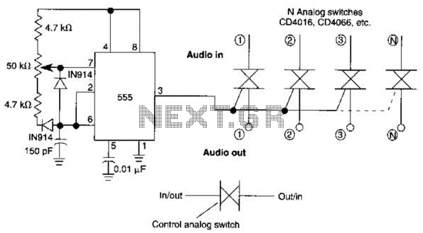
A 555 timer can be configured to simulate a multi-gang potentiometer by controlling the mark-space ratio. The switching rate should be at least twice the maximum expected signal frequency that the potentiometer has to handle. The 555 timer is an...
The CD4538 is a dual Monostable Multivibrator. When triggered, the chip generates a single pulse or a high-low event. The T+ pin (pin 4) of U1a serves as the positive edge trigger input, while the T- pin (pin 5)...
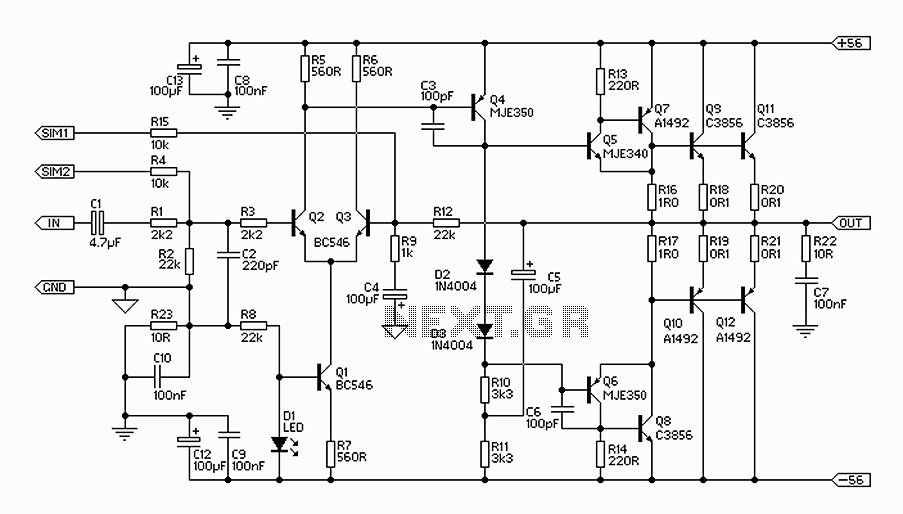
The 300W amplifier circuit presented is a conventional design. It includes connections for the internal SIM and incorporates filtering for RF protection (R1, C2). The input is facilitated through a 4.7µF bipolar capacitor, which offers substantial capacitance in a...
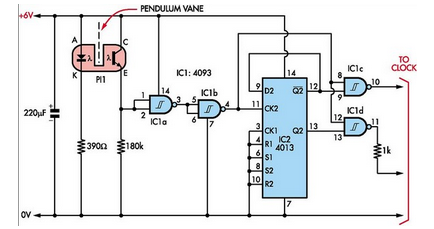
Here is how to build a pendulum-controlled clock that can be made very accurate. Retro? Yes, but it is an interesting project nonetheless. You will need a specific set of components. A pendulum-controlled clock is a mechanical timekeeping device that...
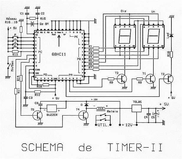
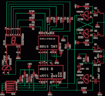
The timer is proposed an effective model for controlling an external load 8A/380V. Equipped with a 68HC11 mu.P associated with an 8 MHz crystal, it can get very precise programmable durations. Two lines are planned: from 0 to 99...