
spider prog content

The described circuit primarily focuses on the interfacing of an AVR microcontroller with a parallel port programmer, specifically the sp12. The schematic involves a simple board that includes a zip-socket for the microcontroller, a 10K pull-up resistor connected to the reset pin, and capacitors for stabilization. The reset circuitry is critical for ensuring reliable operation, as it manages the power-on reset and guards against unintended resets during operation. The use of a low-resistance pull-up resistor ensures that the reset pin is held high during normal operation, while the capacitor can help filter out noise and provide a stable reset signal.
The connection to the Centronics parallel port is established using a standard cable, with considerations made for signal integrity and voltage levels. The integration of the dongle enhances the reliability of the programming interface by ensuring that the programming lines are in a high-impedance state when not actively driven by the sp12 programmer. This reduces the chance of interference and ensures that the microcontroller can communicate effectively with the programming hardware.
The flexibility of the sp12 programmer is a notable feature, allowing users to add support for new microcontroller models easily. This is facilitated by the runtime configuration file, which can be edited to include new devices or customize the programming process. The ability to define fuse settings and prevent accidental lockout of the microcontroller is a significant advantage, particularly for development environments where multiple users may interact with the programming hardware.
Overall, the design emphasizes reliability, flexibility, and ease of use, making it suitable for both novice and experienced users in the AVR microcontroller development community.The avr-gcc/binutils combination is able to provide Intel Hex files, suitable for upload to an AVR uC using sp12. More about that in the Linux section below. If you will be using assembly, then the next thing you want is an assembler, to convert your human-readable assembly into uC-readable machine code.
Tom Mortensen has written a pretty go od one, which is available for Dos as well as Linux. You`ll find it on his page: AVR Studio: AVR Studio 4 is the new professional Integrated Development Environment (IDE) for writing and debugging AVR applications in Windows 9x/NT/2000 environments. AVR Studio 4 supports the following AVR development tools: ICE50, JTAGICE, ICE200, STK500/501/502 and AVRISP.
IAR AVR Assembler: Archive Containing the IAR Assembler Version 1. 50 for the AVR family of microcontrollers. Fully featured command line assembler. Includes Linker and Librarian. Compatible with AVR Studio. Documentation inlcluded in PDF format. The final item on the list is a programmer, to upload the code to the uC. You will need this no matter what language you use. A convenient, fully documented programmer wasn`t available, so we wrote one ourselves. Here you have the diagram for a little board containing just a a zip-socket for the uC, perhaps a crystal or resonator (but there will often be an internal RC clock) and very few other parts, as used by our programmer: Note that the parallel ports of modern PC`s usually provide a rather modest voltage, around 3. 5V. Quite enough for low voltage AVR uC`s, but some devices really do require more, an example being the ATMega161.
But the software is just as suitable for `in circuit` programming. In that case, the target board must allow free access to MOSI, MISO, SCK and Reset. A 10K resistor between the reset pin and Vcc ensures power-on reset and allows sp12 sufficient access: When using the sp12 `stand alone` programming hardware and a plain cable, the 10K/100N time constant on reset isn`t required. The uC does its own start-up delay when Vcc goes high, and that works fine if it is powered by the parallel port.
But I`ve noticed that reset does fail occasionally if power doesn`t switch on cleanly - like when an adapter is plugged in to feed a target board. The time constant on the reset pin solves that, and also guards against spurious resets (which occurred when I used the 1200 in a charging ciruit, where relatively high currents were switched).
A short cable connects the board to the Centronics parallel port of a PC. In most cases a plain cable will do well enough, but Ken Huntington has designed a nice `dongle` to improve the signal quality and make the programming lines high-Z except when sp12 is active. The dongle can be part of the cable, and is perfectly transparent to the software. It has no power requirements, as it receives its Vcc from the port (and passes it on to a low power target board if required).
The reset circuit should at least consist of a 10K resistor between Vcc and the uC`s reset pin. Here is the schematic: Sp12 version 2. 1 is a serial mode (in-circuit) programmer for the AVR family of microcontrollers. When new AVR uCs arrive, you can easily add support for them yourself, by adding a plain text entry to the new runtime configuration file _sp12dev. Editing this file also allows you to customize the way sp12 deals with existing uCs. Customization means, among other things, that you can define the write (high, extended) fuses commands so they won`t touch the bits that can lock you out of your uC.
For instance, the Mega8 and the Tiny15 both allow serial mode access to RSTDISBL, which can take away the resetpin - thus ending serial mode programming access. The Tiny15 also permits writing to SPIEN. If you use the _sp12dev entries as provided, these fuses will never be altered by user errors. Sp12 is one of the few programmers capable of uploading new software to several uCs on a single target, in one
🔗 External reference
Related Circuits
Anyway, Fluffy is a SX programmer for people who have already experimented with PIC chips, and want to try out the Scenix SX family. I built Fluffy because I wanted to experiment with the SX's, but didn't want to...
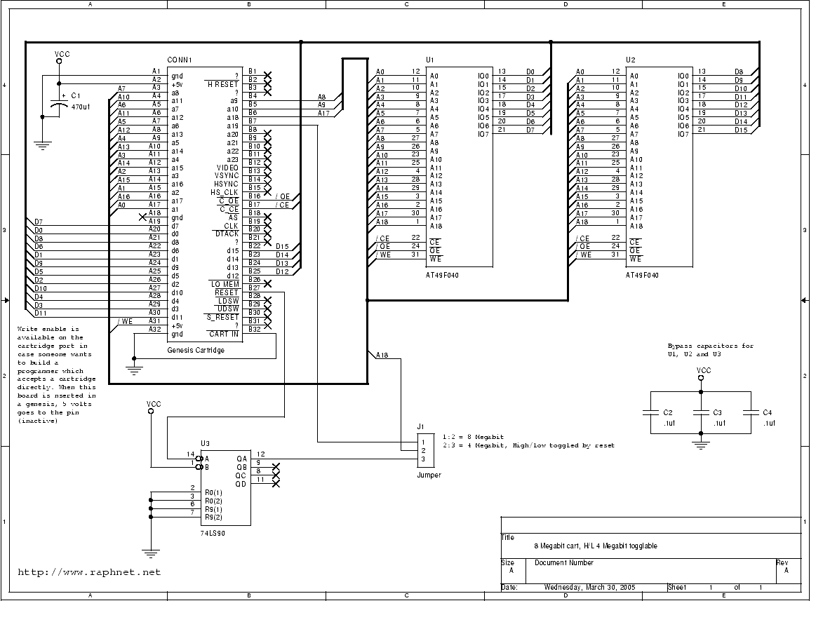
Build a reprogrammable cartridge. Many applications or games can be developed and tested on actual hardware rather than using an emulator. For those interested in Genesis development, the technical documentation available at Zophar serves as a valuable starting point....
Most individuals have likely installed one of the many software tools that facilitate programming the PIC 16C84 on their computers. Among the most popular options is the RIR02 from Silicon Studios. The circuit detailed below is one of the...
The EEprom programmer software supports the following devices 28C16, 28C256, 28C17, 29C256, 28C64. Diode D1 and resistor R1 provide the VDD isolation when programming the 24 pin devices. The jumper J3 must be shorted for 24 pin devices, and...

The PGA203 and isolation amplifier IS0102 form an isolated programmable gain instrumentation amplifier circuit. The PGA203 amplifies the input signal, and the output from the isolation amplifier IS0102 is VOUT. Additionally, a DIN digital optocoupler is used for the...
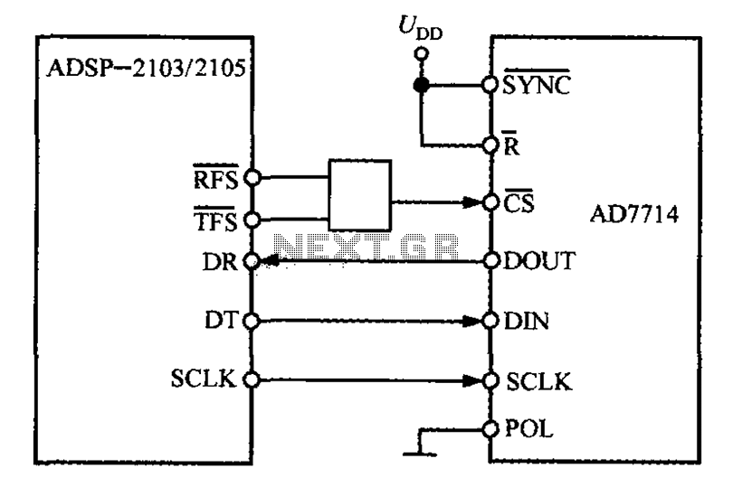
The ADSP-2103 and ADSP-2105 are digital signal processors that interface with the AD7714. When the output is active, the ADSP-2103/2105 configuration includes the RFS non-TES non-terminal set to a low level, while the SCLK terminal is configured for serial...