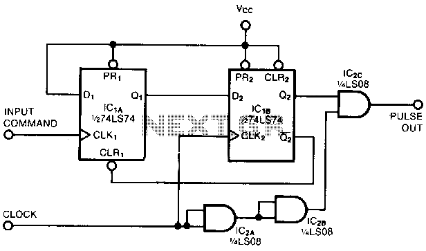
Square-wave-pulse-extractor

This circuit captures a single positive pulse from a square-wave train. After the rising edge of an input command, the pulse-out signal generates a replica of one positive pulse of the clock signal simultaneously with the next rising edge of the clock signal. The zero input command signal sets the Q1 output of flip-flop IC1A. Consequently, the next rising edge of the clock signal sets the Q2 output of IC1B, which enables AND gate IC2C to pass the next positive pulse of the clock signal. AND gates IC2A and IC2B prevent the generation of brief output glitches by delaying the clock signal by two propagation delays.
The circuit operates by utilizing two flip-flops (IC1A and IC1B) and multiple AND gates (IC2A, IC2B, and IC2C) to ensure accurate pulse trapping and signal integrity. Initially, when a positive command signal is detected, flip-flop IC1A is triggered, causing its Q1 output to go high. This transition is crucial as it synchronizes the subsequent operations of the circuit. The next rising edge of the clock signal then triggers flip-flop IC1B, which sets its Q2 output high.
The output from Q2 is directly linked to AND gate IC2C, which is responsible for passing the next positive pulse of the clock signal. This design allows for the precise replication of the clock signal's pulse, ensuring that only one pulse is emitted in response to the command signal.
To mitigate the risk of output glitches, which can occur due to rapid changes in the input signal, AND gates IC2A and IC2B are implemented. These gates introduce a delay of two propagation delays, effectively smoothing out any transient signals that may arise during operation. This delay ensures that the output remains stable and free from unintended brief pulses, which could disrupt the functionality of the circuit.
Overall, this circuit is designed for applications requiring reliable pulse generation from a clock signal, with built-in features to enhance stability and reduce noise, making it suitable for various electronic systems that rely on precise timing and pulse control.This circuit traps a single positive pulse from a square-wave train. Following the rising edge of an input command, the pulse-out signal emits a replica of one positive pulse of the clock signal simultane ous with the clock signal"s next rising edge. The 0 input command signal sets the Ql output of flip-flop "----IClA. Consequently, the next rising edge of the clock signal sets the Q2 output of IClB, which allows AND gate IC2C to pass the clock signal"s next positive pulse. AND gates IC2A and IC2B prevent the generation of brief output glitches by delaying the clock signal by tv seconds (two propagation delays).