
Super boost bass by UA741

The super boost bass circuit utilizes a low-pass filter configuration to effectively attenuate higher frequency signals while allowing lower frequencies to pass through. This is particularly beneficial for audio applications where bass enhancement is desired, such as in home theater systems, car audio setups, or personal audio devices.
The circuit typically consists of passive components such as resistors, capacitors, and sometimes inductors, arranged to define the cutoff frequency. The cutoff frequency is a critical parameter that determines the point at which the filter begins to attenuate higher frequencies. The design can be adjusted to achieve the desired bass response by selecting appropriate component values based on the desired audio characteristics.
In practical applications, the circuit can be integrated with audio amplifiers or used in standalone configurations. The output of the low-pass filter is connected to the audio output stage, ensuring that the enhanced bass frequencies are delivered to the speakers or headphones.
Additionally, the circuit may include features such as gain control to adjust the level of bass enhancement, and it can be designed to operate with various audio sources, providing versatility in its use. Overall, this super boost bass circuit is an effective solution for audio enthusiasts seeking to enrich their listening experience with deeper bass tones.Super boost bass circuit this be low pass filter circuit model,which will low pass filter. By give bass audio that firm then convenient for a person who like.. 🔗 External reference
Related Circuits
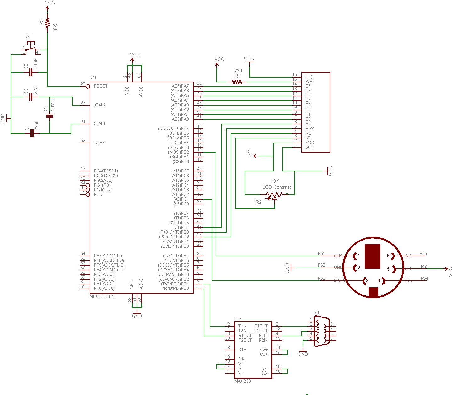
This guide demonstrates how to create a simple terminal using a keyboard, LCD screen, and an 8-bit microcontroller. A portable terminal can be useful for troubleshooting a headless server, building a minicomputer from a WRT, or learning how to...
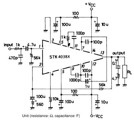
The STK4038-based 60-watt audio amplifier circuit project utilizes the STK4038X audio amplifier IC, designed to create a straightforward yet high-power and efficient audio power amplifier. Manufactured by Sanyo Corporation, this circuit delivers an output power of 60 watts with...
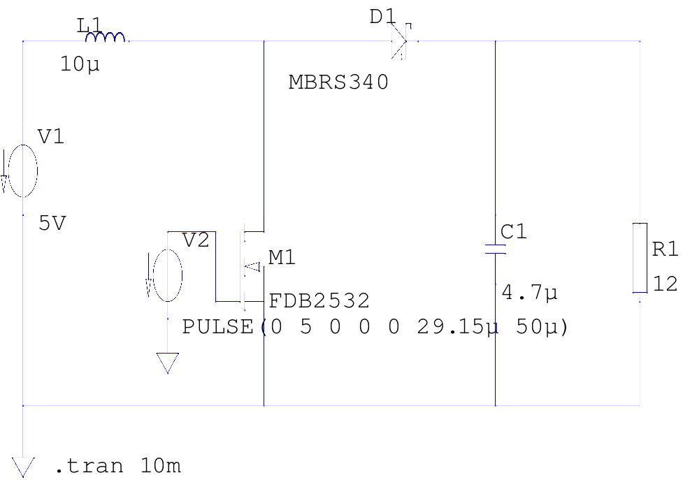
The supply voltage is 5V, and the goal is to increase it to 12V with a load current of 1A, resulting in an output power of 12W. A switching frequency of 20kHz has been selected, requiring a duty cycle...
In battery-powered applications such as cell phones, PDAs, and digital cameras, an integrated DC-DC converter circuit solution provides multiple advantages regarding cost, size, and design complexity. A significant challenge in achieving a fully integrated solution is designing the frequency...
This circuit is a 20W Audio Amplifier kit, based on the TDA2005 IC, a class B dual audio amplifier, specifically designed for car radio applications etc. Power supply - 18 VDC. Output power - 20 W, 4 ?. IC...
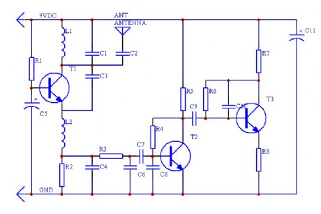
This is a simple RF receiver primarily designed for low-distance digital radio receiver applications. The analog output of this circuit should be connected to a Schmitt-trigger signal conditioning circuit with an appropriate capacitor value (from the collector of T3)....