
Switchmode Constant Current Source

The described circuit operates as a constant current driver for stepper motors, enhancing performance by maintaining adequate torque at various speeds. The LM2575T integrated circuit serves as a crucial component, functioning as a step-down voltage regulator while being adapted to control output current. The inclusion of a switch-mode topology allows for efficient energy conversion, minimizing heat generation and improving overall system efficiency.
In this circuit, the current sensing mechanism is facilitated by the resistor R1, which is placed in series with the load (the stepper motor). The voltage drop across R1 is proportional to the current flowing through it, and this voltage is monitored by transistor Q1. When the sensed current exceeds a predetermined threshold, Q1 activates, adjusting the feedback loop of the LM2575T to limit the output current to the desired level. This feedback mechanism ensures that the motor receives a consistent current, thus preventing stalling and maintaining performance even at higher speeds.
The use of adjustable resistor VR1 allows for fine-tuning of the output current, which is critical for accommodating different stepper motor specifications. By setting VR1 appropriately, the user can optimize the driving conditions for a specific motor, ensuring that it operates efficiently across its entire speed range.
Overall, this circuit design exemplifies an effective approach to driving stepper motors with a constant current supply, leveraging the benefits of switch-mode technology to deliver reliable performance. The adaptability of the circuit to various motor types further enhances its utility in diverse applications, making it a valuable solution for engineers and designers working with stepper motor systems.Operating a stepper motor using a fixed (constant) voltage supply results in poor torque at high speeds. In fact, stepper motors tend to stall at fairly low speeds under such conditions. Several approaches can be used to overcome this problem, one of which is to use a constant current supply in place of the more conventional constant voltage suppl
y. A disadvantage of many constant current supplies is that simple circuits are inefficient but that doesn`t apply to switchmode supplies such as the circuit shown here. Basically, this circuit is a conventional switchmode regulator adapted for constant current output and is specially designed for stepper motor drivers - although it could be used for other applications as well.
The circuit works as follows: IC1 (LM2575T) and its associated components (D1, L1, C1, etc) operate as a switchmode power supply. Normally, for constant voltage operation, the output is connected - either directly or via a resistive divider - back to the feedback input (pin 4) of IC1.
In this circuit, however, Q1 senses the current flowing through R1 and produces a corresponding voltage across R3. This voltage is then fed to pin 4 of IC1. As a result, the the circuit regulates the current into a load rather than the voltage across the load.
Only one adjustment is needed: you have to adjust VR1 for optimum stepper motor performance over the desired speed range. The simplest way to do this is to measure the motor current at its rated voltage at zero stepping speed and then adjust VR1 for this current.
The prototype worked well with a stepper motor rated at 80O per winding and a 12V nominal input voltage. Some components might have to be modified for motors having different characteristics. 🔗 External reference
Related Circuits
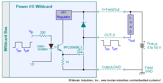
The embedded I/O board offers isolated high voltage switch inputs and eight high current, high voltage DC outputs. It utilizes optically isolated, open drain N-MOSFET transistors functioning as solid state relays (SSR) to control various resistive or inductive loads....
The following circuit illustrates a High Voltage, Low Current Supply. Features: This circuit is utilized for applications such as biasing gas-discharge tubes, radiation detectors, and similar devices. The High Voltage, Low Current Supply circuit is designed to provide a stable...
The drawback of the circuit mentioned is that the operational amplifier (op-amp) supply is connected to the high voltage (HV) supply. Most op-amps are limited to approximately 30V for their supply voltage, which prevents the circuit from functioning with...
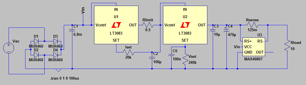
The circuit utilizes standard analog control through potentiometers while incorporating digital readouts for voltage and current measurements. Despite reviewing power supply unit (PSU) video tutorials, the single LT308x configuration with a transistor limiter did not function as expected in...
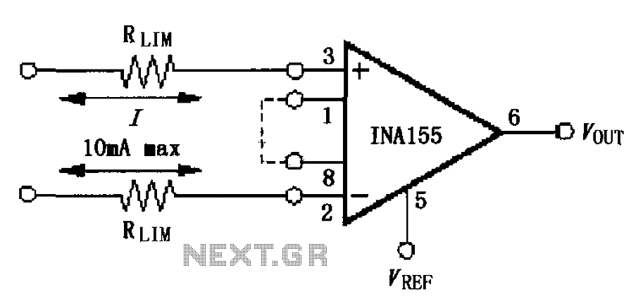
The input current protection circuit is illustrated in FIG, utilizing INA155/156. The INA155 features internal electrostatic discharge (ESD) protection diodes that become active when the input voltage exceeds the supply voltage by 500mV. In this scenario, the protection diodes...
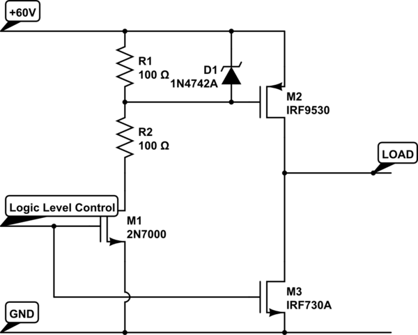
Construct an H-bridge specifically for reversing current, as speed control is managed separately. Is it feasible to connect two N-channel MOSFETs and two P-channel MOSFETs to an IO pin from the microcontroller (with appropriate resistors), or is the process...