
Symmetrical power supply 3-20V

The L165 integrated circuit is designed to provide a stabilized symmetrical power supply derived from a single asymmetrical power source. This configuration is particularly useful in applications requiring dual polarity power supplies, such as operational amplifiers or analog signal processing circuits. The output voltage from the L165 is nominally half of the input voltage, making it essential to consider the input voltage levels to ensure the desired output is achieved.
In constructing the circuit, it is crucial to incorporate ripple filter capacitors (C1, C2, C3, and C4) to attenuate any noise present in the power supply. Capacitors C1 and C2 should be positioned as close as possible to the L165 IC to minimize inductive effects and voltage drops that may occur in the PCB traces. Capacitors C3 and C4 should be located near the output jacks to provide local decoupling and further enhance the stability of the power supply.
The PCB layout must be designed with adequate trace widths to handle the maximum current of up to 3 amperes. This is critical to prevent overheating and ensure reliable operation. The traces should be calculated based on the current carrying capacity and the permissible temperature rise, following IPC standards for PCB design.
Proper thermal management is also necessary for the L165 IC, which may require a heatsink to dissipate heat generated during operation. The heatsink should be selected based on the thermal resistance of the IC package and the expected power dissipation, ensuring that the junction temperature remains within safe limits.
The L165 can function as a voltage amplifier, specifically amplifying the voltage at the junction between resistors R1 and R2. This characteristic can be leveraged in applications requiring signal amplification alongside power supply functionality.
Alternatively, the L165 can be replaced with the TCA1365 IC. When using the TCA1365, it is essential to connect pins 3 and 4 together to ensure proper operation. Additionally, a 220pF capacitor should be connected between pins 5 and 6 to optimize performance and stability. This flexibility allows designers to choose the appropriate IC based on specific application requirements and availability.The compact 5 pin L165 IC general a stabilized symmetrical power supply from a single asymmetrical power supply. The output voltage is however, half of the input voltage. One needs to add the ripple filter capacitors C1, C2, C3 and C4 and some resistors for setting the symmetry.
In constructing the circuit, place the capacitors C1 and C2 as close to the IC as possible. On the other hand, place the capacitors C3 and C4 close to the output jacks. Make sure that the circuit lines on the pcb are properly dimensioned to handle high current levels. Current levels up to 3 amperes can flow through the circuit. Additionally, provide a proper heatsink for the L165 IC. The L165 IC can also be viewed as a voltage amplifier. It amplifies the voltage appearing at the junction between R1 and R2. One cas also replace the IC with TCA1365. However, when using the TCA IC, pins 3 and 4 have to be connected together. Also connect a 220pF capacitor between pins 5 and 6. 🔗 External reference
Related Circuits
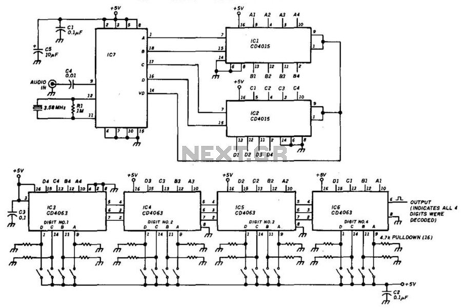
This decoder will respond to a preselected 4-digit DTMF number. IC7 is a Radio Shack IC device (part #276-1303). The logic is all CMOS. The digits are selected by SW1 and SW2, a pair of 8-position DIP switches. The described...
A mixer has been purchased without a power supply unit (PSU). The user does not require the 48V phantom power and is inquiring if an 18V DC wall adapter can be used instead. Additionally, the user seeks information on...
To commemorate the hundredth design posted on this website and to meet the requests of numerous correspondents desiring a more powerful amplifier than the 25W MosFet, a 60 - 90W high-quality power amplifier design is presented. The circuit topology...
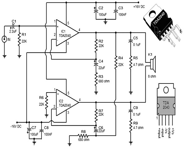
This small and compact stereo amplifier is powerful and can easily replace a broken amplifier or be used in new constructions, or to create an active speaker, when combined with a preamplifier. Its remarkable features make it a true...
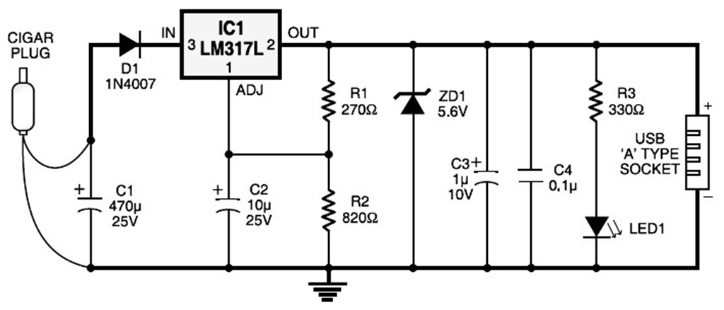
A USB port is capable of supplying more than 100 mA of continuous electric current at 5V to peripherals connected to the bus. This feature allows a USB port to power 5V DC-operated small electronic devices without issues. Many...
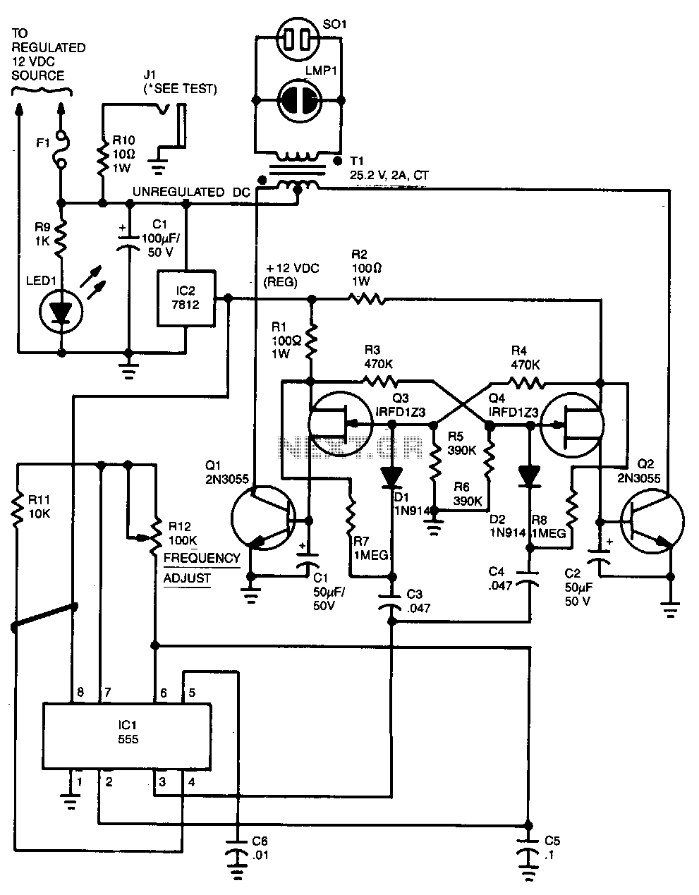
Capacitor C5 and potentiometer R12 determine the frequency of the output signal at pin 3 of IC1, the 555 oscillator. The output signal is differentiated by C3 and C4 before it is input to the base of power transistors...