
Symmetrical power supply circuit electronic project

The circuit for a symmetrical power supply typically consists of an operational amplifier configured in a non-inverting mode, with resistors R1 and R2 forming a voltage divider network. The primary function of the operational amplifier in this configuration is to maintain a stable reference voltage at its non-inverting input, which is derived from the voltage divider formed by R1 and R2.
In this setup, R1 is connected from the positive supply voltage to the inverting input of the operational amplifier, while R2 is connected from the inverting input to ground. The output of the operational amplifier is fed back to the inverting input, creating a closed-loop feedback system. This feedback mechanism is essential for ensuring that the voltage at the inverting input matches the voltage at the non-inverting input, thus stabilizing the output voltage.
The output voltages of the symmetrical power supply are determined by the values of R1 and R2. When R1 and R2 are equal, the output voltages will be equal in magnitude but opposite in polarity, achieving a symmetrical output. This symmetry is critical for applications requiring balanced power supply rails, such as in audio amplifiers, operational amplifier circuits, and analog signal processing.
To further enhance the performance of the symmetrical power supply, it may be beneficial to add bypass capacitors at the power supply pins of the operational amplifier. This addition helps to filter out high-frequency noise and provides a more stable voltage reference. Additionally, incorporating a precision voltage reference can improve the accuracy of the output voltages.
Overall, this symmetrical power supply circuit is a fundamental design that leverages the properties of operational amplifiers and resistive voltage dividers to achieve balanced output voltages suitable for various electronic applications.A symmetrical power supply, can be designed using this circuit diagram. This symmetrical power supply is designed using a simple operational amplifier and some classic electronic components Resistances R1 and R2 form a high impedance voltage divider. Operational amplifier makes sure that artificial potential mass is the same as the voltage at the common point between R1 and R2. The ratio of R1 and R2 determine the relationship between the two output voltages, if R1 and R2 are identical, the two output voltages are symmetrical. 🔗 External reference
Related Circuits
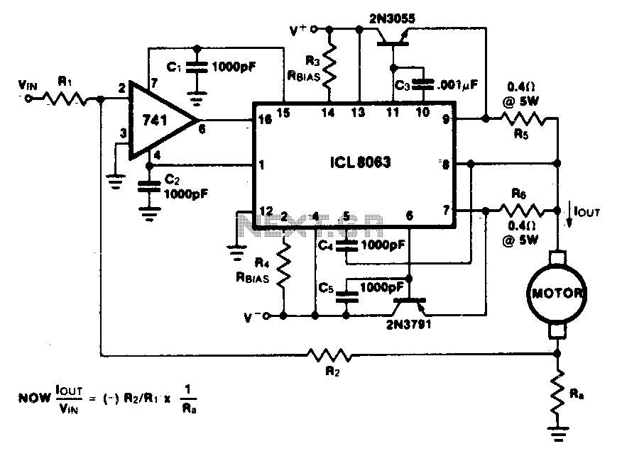
This minimum device circuit can be used to drive DC motors where there is some likelihood of stalling or lock-up. If the motor locks, the current drive remains constant, and the system does not destroy itself. This circuit is designed...
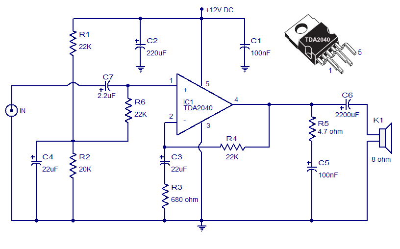
The Car Stereo Amplifier Circuit featuring the TDA2040 is presented here. The TDA2040 is a monolithic integrated audio amplifier that operates in Class AB mode. This integrated circuit includes built-in short circuit protection and thermal management features, allowing it...
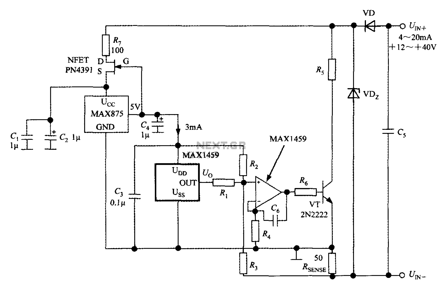
A 4 to 20 mA current transmitter circuit is implemented using the MAX1459, as illustrated in the accompanying figure. The output voltage from the programmable gain amplifier (PGA) is supplied to a spare amplifier chip, and subsequently, an external...
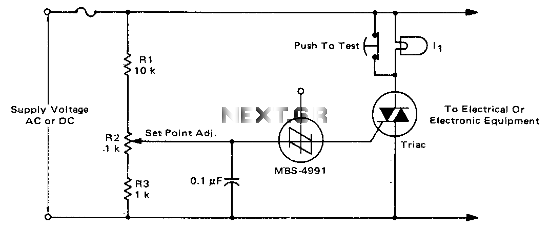
For positive protection of electrical or electronic equipment, this circuit is designed to guard against excessive supply voltage. An electronic crowbar circuit can rapidly create a short circuit across the power lines due to improper switching, wiring issues, short...
This application note outlines the design of a PC-based, 14-bit data acquisition system. It adopts a systematic approach, incorporating all essential components: analog, digital, hardware, and software. The document elaborates on each phase, emphasizing the testing of individual systems...
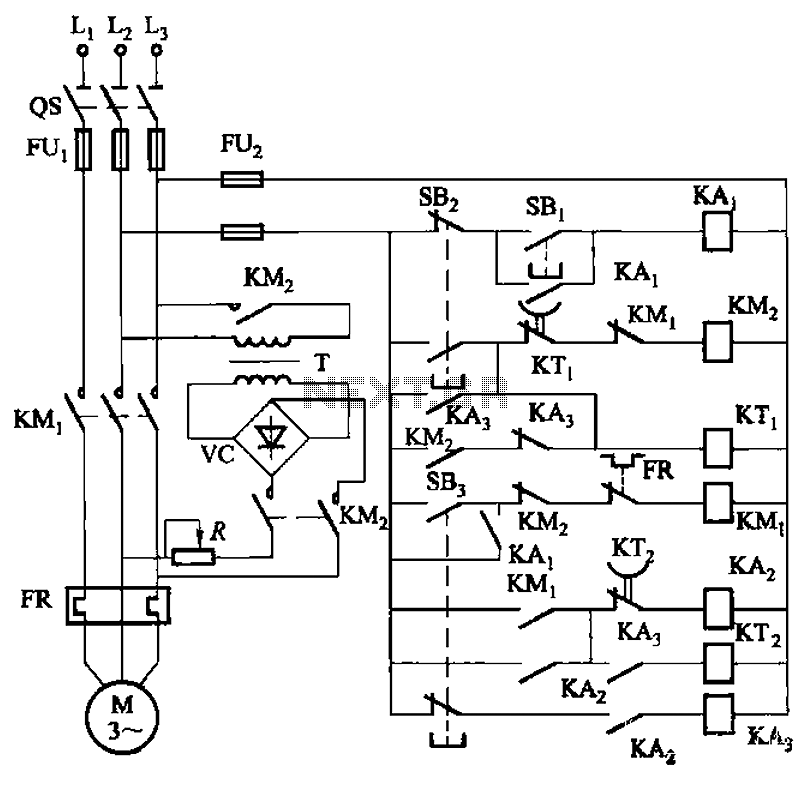
The circuit depicted in Figure 3-143 demonstrates a braking mechanism for a motor that operates effectively during normal shutdown and jog operations. The circuit includes several components, such as the start button (SBz), stop button (SBz), and jog button...