
Tape monitor the direction of movement

The circuit operates by utilizing a rectangular pulse generator as the central component, which generates a series of pulses at a specified frequency. The frequency can be fine-tuned through the selection of capacitor C1 and resistor R1, allowing for flexibility depending on the application requirements. The D flip-flop (T077) serves as a binary counter, effectively halving the frequency of the incoming pulse signal, which is essential for controlling the timing of the LED indicators.
The decoding circuit, constructed from additional NAND gates (YF5 to YF8), is responsible for interpreting the output of the D flip-flop and determining which LEDs should be activated based on the current state of the tape direction. The arrangement of the NAND gates ensures that the correct LED lights up according to the direction of the tape movement, whether it is playing forward or rewinding.
The mechanical switches (K1 to K3) are strategically placed to allow user interaction, enabling the selection of different playback functions. Each switch is connected to the circuit in such a way that pressing a button generates a unique trigger signal, which is then processed by the flip-flop and the NAND gates to control the corresponding LED output.
In the event that the STOP button is engaged, the circuit is designed to enter a standby state, where the LEDs exhibit a flashing behavior. This feature serves as a visual indicator to the user that, while the device is powered, it is not currently in motion, thereby providing clear feedback regarding the operational status of the tape recorder. As shown in FIG display circuit for the tape direction. The rectangular pulse generator circuit, D flip-flop (T077), the decoding circuit, the light emitting diode LED1 ~ LED4 and other components. By the rectangular pulse generator NAND gate YF1 ~ YF4 composition, the frequency of the output signal is 1 ~ 3Hz, changing C1, R1 adjustable corresponding frequency value. T077 connected as counter states, to signal a rectangular pulse generator output is divided by two. Decoding circuit consists of NAND gates YF5 ~ YF8, its output signal to control the light-emitting diode display, so that when the recorder is LED1 ~ LED4 turn light, indicating the tape running direction.
The moving direction of the light emitting point depends on the polarity of the output pulse of the pulse generator. Positive pulse circuit NAND gate YF1 output, the output of NAND gate YF3 negative, FF, PLAY button connected to the pulse switch K1 ~ K3 mechanically recorder respectively REW, which when pressed when a function key, the corresponding trigger signal will be added to the trigger, the light emitting diode emitting in the appropriate form, showing the direction of movement of the tape.
If you press the STOP key to display the state of the circuit is broken, only one pair of light-emitting diodes to the oscillation frequency of the pulse generator intermittently flashing, indicating that although the recorder is turned on, but the tape does not move.
Related Circuits

This circuit illustrates a standard over/under-voltage fault monitor designed for a single power supply. The upper trip points, which control OUT 1, are set at 5.5 V with a hysteresis of 100 mV (Wu = 5.55 V, L =...
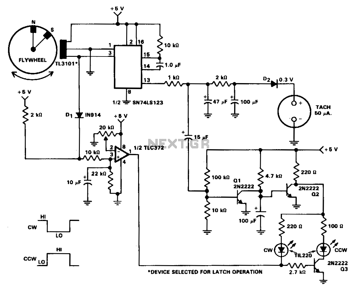
In machine and equipment design, certain applications necessitate the measurement of both shaft speed and direction of rotation. The circuit of a tachometer, which also indicates the direction of rotation, is illustrated. A flywheel is equipped with two magnets...
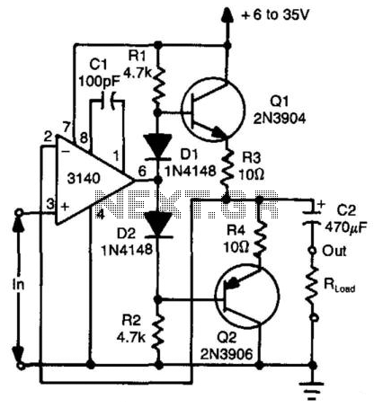
Using two transistors (Q1 and Q2), a bidirectional operational amplifier can source or sink up to 50 mA. Diodes D1 and D2 provide biasing for Q1 to eliminate "dead-zone" effects. The described circuit utilizes two transistors, Q1 and Q2, configured...
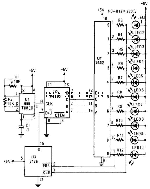
A 555 timer controls a 74190 up/down counter. The 74190 drives a BCD decoder driver 7442. The 7476 is utilized to reverse the count at 0 and 9, resulting in an up-down-up-down counting sequence. The circuit utilizes a 555 timer...
Sending Morse on a rig without a sidetone is not impossible, but is not particularly pleasant either. This battery-powered monitor has been designed to provide an audible indication of keying for those whose rigs lack a CW sidetone. Its...

This AC Power Monitor continuously monitors the AC power line voltage for under-voltage conditions and missing cycles. When it detects a total of 5 or 6 consecutive anomalies, it triggers an alert. The AC Power Monitor is designed to provide...