
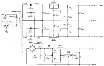
Telephone Amplifier Circuit

Section Ul-a operates as a high-gain inverting voltage amplifier, effectively transforming weak signals from the phone line into amplified outputs. The inductively coupled inductor LI, constructed from 250 turns of fine, enamel-coated wire on an iron core, serves as the primary interface with the phone line. The operational amplifier (op amp) receives the signal generated by the inductor, which is typically in the millivolt range, through capacitor CI and resistor R1.
Capacitor CI plays a critical role in the feedback loop, providing negative feedback that stabilizes the amplifier's response at high frequencies. This feedback mechanism is vital for maintaining signal integrity and preventing unwanted oscillations. Resistor R3 is equally important as it sets the low-frequency gain of the amplifier. Without R3, the amplifier could enter saturation, resulting in distorted output signals.
Following the amplification stage, op amp Ul-b is configured as a difference amplifier. This configuration allows it to compare the output from Ul-a with a reference voltage, typically set to half of the supply voltage. The difference amplifier enhances the signal by focusing on the voltage variations rather than absolute values, which is crucial for applications requiring precision signal processing.
Transistor Q1 operates in a common-collector configuration, providing a buffer that ensures the amplified signal is adequate to drive the connected speaker. This configuration allows for high input impedance and low output impedance, making it suitable for interfacing with the speaker without significant signal loss. Capacitor C5 is strategically placed to filter out any DC offset that may arise from the transistor's output, ensuring that only the desired AC signal reaches the speaker. This filtering is essential for maintaining audio quality and preventing distortion in the output sound. Section Ul-a is configured as a high-gain inverting voltage amplifier that is inductively coupled to the phone line via LI. Inductor LI is a homemade unit that consists of 250 turns of fine, enamel-coated wire that is wound on an iron core.
The op amp receives the few mV produced by LI via. CI and Rl and amplifies the signal. Capacitor CI acts as the negative-feedback component that limits the circuit`s high-frequency gain, while R3 limits the low-frequency gain. Resistor R3 is particularly important because without it, the amplifier would saturate. Op amp Ul-b is configured as a difference amplifier. It receives a signal from Ul-a via 03 and R4 and amplifies the difference between it and half of the supply voltage. Transistor Ql is configured as a common-collector amplifier ensuring sufficient signal to drive the speaker.
Capacitor C5 is used to remove any dc component provided by transistor Ql.
Related Circuits
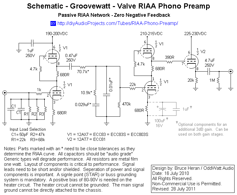
This project has been in development for over a year, initially postponed due to concerns about design complexity and the availability of high-quality phono preamps. The objective was to create a preamp that would deliver performance comparable to commercial...
The circuit is an amplifier with bias at cutoff. Transistor Q5 functions similarly to a grid-leak detector. In the absence of a subcarrier input, the demodulator is disabled, preventing any signals from passing through. It is essential for the...
This site serves as a collection of useful information that the author wishes to retain, with the occasional inclusion of pages that may be of interest to others. The author has documented the retrofit of the Boxford 125 TCL...
This bench power supply features three solid-state DC power supplies. The first supply provides an output of 1.5 to 15 volts at 1 ampere. The second supply offers a range of -1.5 to -15 volts at 1 ampere. The...
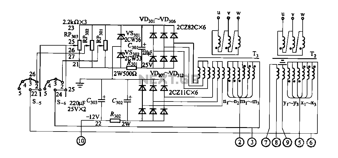
FGDF-3 is a three-phase low-temperature iron plating power supply circuit, while the KGDF-3 is a single-phase low-temperature iron plating power supply device that encompasses all the characteristics of the power supply unit. This design allows for an even distribution...
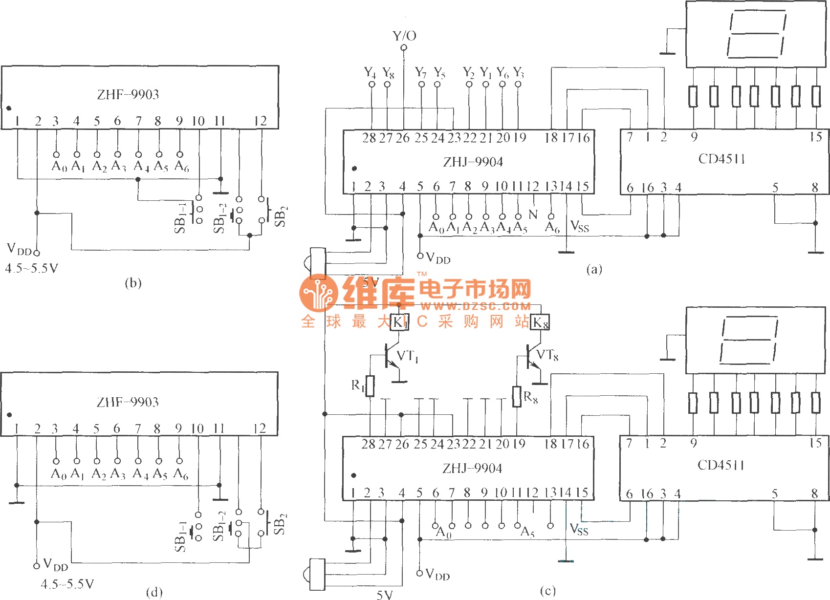
This is an eight-way signal remote control selection circuit composed of ZHJ-9904. It includes a remote control transmitter circuit, an eight-way switch control circuit, and a remote control transmitter. The eight-way signal remote control selection circuit utilizing the ZHJ-9904 is...