
Telephone Ringer

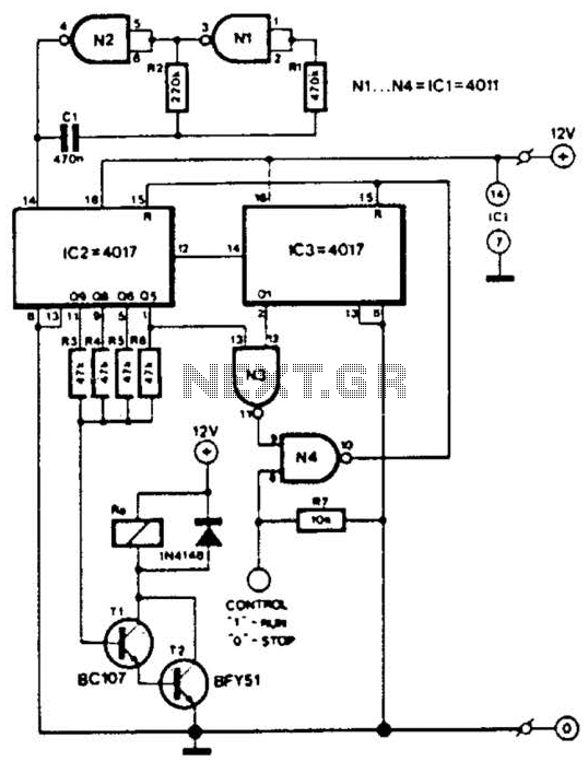
This electronic ringer circuit represents a modern solution for generating ringing tones in telecommunication devices. The use of a NAND Schmitt trigger as a relaxation oscillator allows for precise control over the frequency output, which is critical for achieving the desired sound characteristics. The circuit's design incorporates multiple oscillators and frequency dividers to create a complex but reliable waveform that adheres to standard ringing patterns.
The flexibility provided by adjustable frequency settings allows for customization, catering to different user preferences or applications. The choice of components, such as stable polyester-film capacitors for frequency selection and X7R-ceramic types for decoupling, ensures that the circuit maintains performance under varying conditions. The inclusion of a rectifier also enhances reliability by safeguarding against incorrect power supply connections.
Overall, the circuit's architecture, including the bridge configuration of the NAND gates, maximizes output volume, making it suitable for various applications, including telephones and alarms. This design exemplifies the integration of digital logic and analog components to achieve a functional, user-friendly electronic ringer system.This circuit generates the sound of the electronic ringer found in modern telephones, supplanting the 2-bell electromechanical ringers used previously. The ringing pattern follows the United States convention of 2 seconds on, and 4 seconds off. During the "on" interval, the tone alternates between two selectable frequencies at a rate of 20Hz. Refe ring to the schematic, NAND Schmitt trigger U1A is configured as a relaxation oscillator, adjusted with RV1 for a 40Hz waveform at test point TP1. This waveform is divided by flip-flop U2A to provide a 20 Hz, 50-percent duty cycle square wave at U2A`s Q output, and a complimentary square wave at U2A`s Q-not output.
When U2A`s Q output is high, the relaxation oscillator formed by U1B is enabled. When U2A`s Q-not output is high, the relaxation oscillator formed by U1C is enabled. NAND gate U1D provides an OR function for the two oscillator outputs, and drives flip-flop U2B, which divides the waveform by two to ensure a 50 per-cent duty cycle. The resulting waveform at U2B`s Q output is a square-wave that alternates between two audible frequencies at a 20Hz rate.
The pitch of these frequencies are individually adjustable from approximately 500Hz to 2500Hz with RV2 and RV3, and may be selected for a suitable sound output. A frequency divider chain consisting of U4, U5 and U6 is driven from the 20Hz waveform at U2A`s Q-not output.
U4 and U5 provide a frequency division of 40, resulting in a 0. 5Hz square wave at U5B pin 13. This square wave drives U6, which is configured as a divide-by-3. U6`s "0" output is a 0. 167Hz waveform which is at a high state for 2 seconds, and a low state for 4 seconds. Paralleled gates U3A and D, driven by U2B`s Q output, drive one side of the piezo audible transducer, as well as the inputs of two additional paralleled gates, U3B and C. U3B and C`s outputs drive the other side of the transducer. All four of U3`s NAND gates are enabled by U6`s "0" output, resulting in a 2-second-on, 4-second-off tone pattern.
U3`s bridge configuration doubles the voltage that appears across the transducer, producing ample volume. If desired, the piezo transducer may be substituted with a 100-ohm-impedance dynamic loudspeaker. The power supply voltage is not critical and may vary between 6 and 12 volts. However, it should be regulated to prevent frequency variations in the circuit`s oscillators. The three frequency-selection capacitors should be stable polyester-film types, and the 0. 1uF decoupling capacitors should be X7R-ceramic types. The 1N4001 rectifier protects the circuit from power supply polarity reversal. Layout is not critical, however, the 0. 1uF decoupling capacitors should be located as close as possible to their respective ICs. 🔗 External reference
Related Circuits

A compact, inexpensive and low component count telecom headset can be constructed using two readily available transistors and a few other electronic components. This circuit is very useful for hands-free operation of EPABX and pager communication. Since the circuit...
The TEA5711 is a high-performance Bimos integrated circuit designed for use in AM/FM stereo radios. It integrates all necessary functions, including the AM and FM front-end, AM detector, and FM stereo output stages. The TEA5711 is engineered to provide a...
The Link circuitry is simple and efficient, employing just two integrated circuits (ICs), a few transistors, and common components. It operates on 12 volts and is easy to assemble. This intercom system can connect various locations such as the...
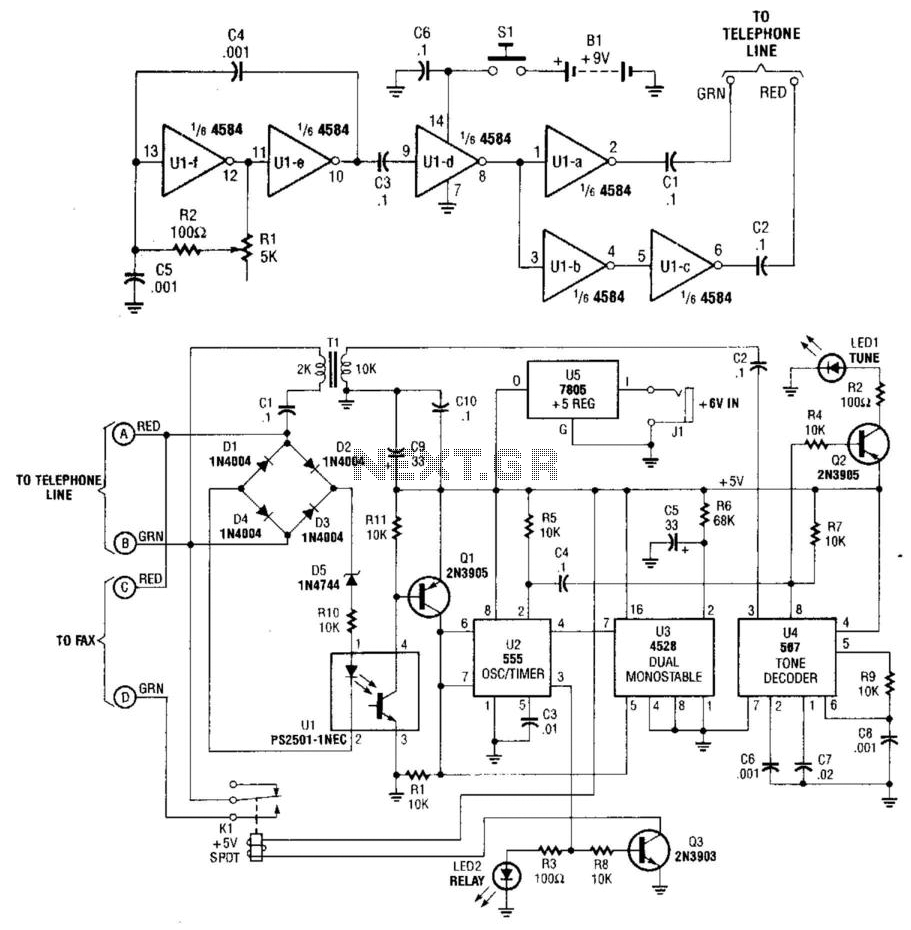
This system uses a transmitter operating at approximately 100 kHz to control a remote receiver. A line splitter can connect the transmitter to the active telephone line. The transmitter is a CMOS oscillator equipped with output buffer stages to...
This circuit is designed for a small private telephone installation. The ringing tone sequence consists of 400 ms on, 200 ms off, 400 ms on, and 2 ms off. In the accompanying diagram, N1 and N2 create an oscillator...
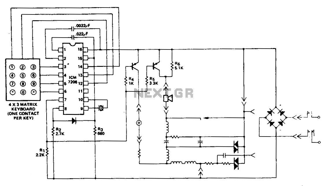
This encoder utilizes a single contact per key keyboard and manages all other switching functions electronically. A diode connected between terminals 8 and 15 limits the output to no more than 1 V negative concerning the negative supply, Vss....