
Temperature ControlCircuit using Microcontroller and Heater Driver

The temperature control circuit utilizes the LM35DZ, a precision analog temperature sensor that outputs a voltage proportional to the temperature in degrees Celsius. This sensor operates within a range of -55°C to +150°C, providing a linear output of 10 mV/°C. The analog signal from the LM35DZ is fed into the PIC16F877 microcontroller, which features an integrated 10-bit A/D converter. The microcontroller processes the analog temperature data, converting it into a digital signal for further manipulation and control logic execution.
The PIC16F877 is programmed to monitor the temperature readings and compare them against predefined thresholds. Based on this comparison, the microcontroller generates control signals to activate or deactivate the heater driver, which in this case is the IRL1004. This MOSFET driver is capable of handling high currents and voltages, making it suitable for controlling heating elements. The IRL1004 operates efficiently due to its low on-resistance, ensuring minimal power loss during operation.
The circuit is designed with appropriate power supply decoupling and filtering to ensure stable operation of the microcontroller and the sensor. Additionally, it includes necessary protection components, such as diodes, to safeguard against voltage spikes that may occur during the switching of the heater. Overall, this temperature control circuit provides a reliable and efficient solution for maintaining desired temperature levels in various applications.The electrical circuit diagram of this temperature control circuit consists 3-pin analog temperature sensor (LM35DZ), a built-in A/D converter microcontroller (PIC16F877), and the heater driver (IRL1004) 🔗 External reference
Related Circuits
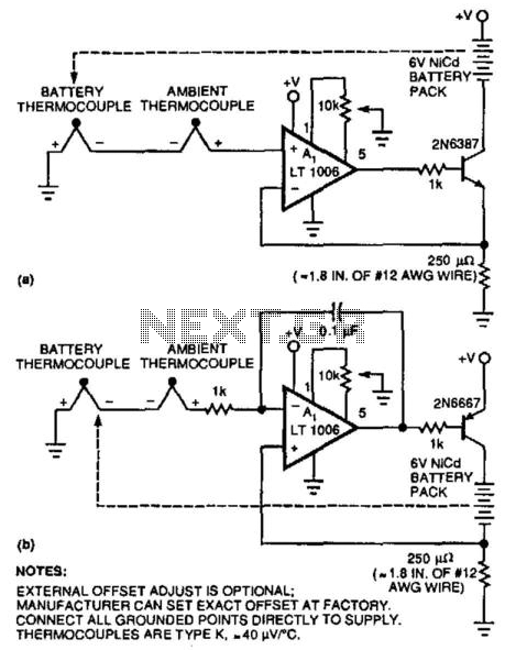
Two simple circuits enable NiCad battery charging based on the temperature differences between the battery pack and the ambient temperature. This method allows for fast charging by sensing the temperature rise that occurs after charging is complete when the...
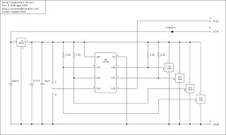
The microcontroller program is designed to support two communication protocols: the one-wire bus utilized by the DS1820 temperature sensor and the serial protocol used for communication with a computer. Upon power-up, the program retrieves data from the temperature sensors...
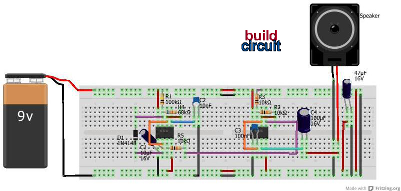
This project involves a simple light-activated police siren utilizing a light-dependent resistor (LDR) and an NE555 timer. It is advisable to complete some preliminary projects before attempting this one. The NE555 timer, configured in slow astable mode with a...
The PR4403 is an advanced version of the PR4402 40mA LED driver. It features an additional input known as LS, which can be activated by pulling it low to illuminate the LED. This functionality simplifies the construction of an...
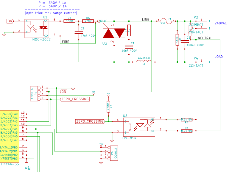
The resistance of the heater is constructed using 9 Ω nichrome wire with a diameter of 3 mm. When supplied with 240V (rms) voltage, this configuration results in a current of 25A (rms). Access to a mains line that...
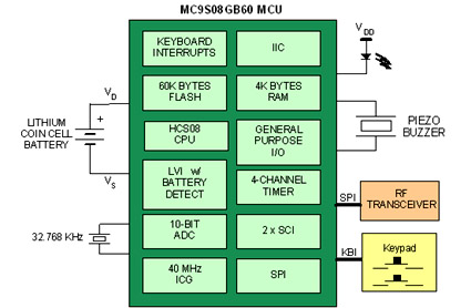
Battery-powered devices, such as electric toothbrushes, shavers, cell phones, PDAs, MP3 players, and remote controls, are integral to daily life. Consequently, power management has become a critical consideration for embedded designers. Microcontrollers (MCUs) provide various methods for managing power...