
Temperature controlled relay circuit

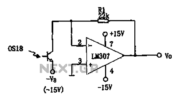
The temperature-controlled relay circuit operates by monitoring the ambient temperature and activating or deactivating a connected load based on predefined temperature thresholds. The core components of the circuit typically include a temperature sensor, a relay, and a control unit, which may consist of an operational amplifier or a microcontroller.
The temperature sensor, often a thermistor or an LM35, detects changes in temperature and converts this information into an electrical signal. This signal is then fed into the control unit, which processes the input and determines whether the temperature is above or below the set point. If the temperature exceeds the upper threshold, the control unit energizes the relay, closing the circuit and powering the connected load, such as a heater or fan. Conversely, if the temperature falls below the lower threshold, the relay deactivates, turning off the load.
To ensure precision, the circuit may incorporate hysteresis, which prevents rapid on-off cycling of the relay near the set point. This is achieved by setting two distinct temperature thresholds: one for activating the load and another for deactivating it. The use of a relay allows for high-power devices to be controlled safely, isolating the low-power control circuit from the high-voltage load.
For applications requiring user interaction, a potentiometer can be included to allow for easy adjustment of the temperature set points. Additionally, LED indicators may be integrated to provide visual feedback on the operational status of the circuit, indicating when the load is active.
Overall, this temperature-controlled relay circuit is versatile and can be adapted for various applications, including HVAC systems, incubators, and refrigeration units, ensuring efficient thermal management in an array of environments.This temperature controlled relay circuit is a simple yet highly accurate thermal control circuit which can be used in applications where automatic tempera. 🔗 External reference
Related Circuits
The objective is to enhance information transmission through the use of articles. Please contact us via email at [email protected] within 15 days if there are any issues related to article content, copyright, or other concerns. Prompt action will be...
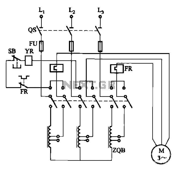
The circuit illustrated in Figure 3-47 involves a three-phase AC motor that is initially connected through a step-down autotransformer. To initiate operation, the power switch is closed, and the operating handle is pushed to the start position. Once the...
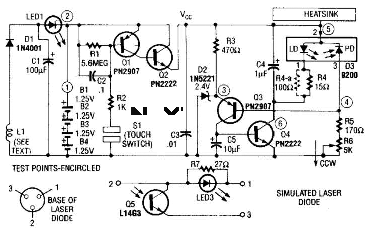
A laser diode TOLD9200 (Toshiba) serves as a source of laser light. Q3, Q2, and SI constitute a touch switch to control the laser. L1 is an RF pickup coil designed to extract energy from an RF-type battery charger....
The video amplifier depicted in the diagram is a widely recognized design that is both simple and highly effective. However, the transistors are susceptible to damage if the potentiometers (black level and signal amplitude) are set to their extreme...
The LED current drive is regulated and programmable, which eliminates the need for current-limiting resistors. The integrated circuit (IC) features an adjustable voltage reference and an accurate ten-step voltage divider. The LED current drive circuit is designed to provide precise...
The circuit described is a photoelectric receiver amplifier designed to amplify the electrical signals generated by photodiodes or phototransistors in optoelectronic devices. When the intensity of incident light varies, the photosensitive device generates a corresponding voltage or current. The...