
Temperature limit Relay

Part List
R1=4.7 K ohm TH1=NTC thermistor 500 ohm.....9 K ohm Q2=BC214L
R2=2.2 K ohm D1-2=1N4148 RL1=12V Relay >120 ohm
RV1-2-3=10 K ohm pot. D3=1N4001
This circuit operates as a temperature-sensitive switch utilizing an NTC (Negative Temperature Coefficient) thermistor, TH1, which decreases its resistance as the temperature increases. The resistance range of the thermistor, specified as 500 ohms to 9 k ohms, is critical for ensuring accurate temperature detection within the desired operating range.
The primary function of the circuit is to determine whether the temperature is above or below a predefined threshold. The variable resistor RV1 allows for calibration of the circuit to set a reference voltage at the junction of RV1 and TH1. This is essential for establishing the mean temperature point at which the circuit will trigger an output response.
The output stage of the circuit is driven by transistor Q2 (BC214L), which acts as a switch to control the relay RL1. The relay is rated for 12V and has a minimum coil resistance of 120 ohms, allowing it to be activated when the voltage at the collector of Q2 exceeds a certain level, indicating that the temperature has crossed the set threshold.
Resistors R1 and R2 are used to form a voltage divider, which helps to create the necessary biasing conditions for Q2. The diode components D1 and D2 (1N4148) serve as protection diodes to prevent back EMF from the relay coil from damaging the circuit when the relay is deactivated. D3 (1N4001) is likely used for additional protection or rectification purposes within the circuit.
The overall design emphasizes stability and reliability, ensuring that the circuit can effectively monitor temperature changes and activate the relay in response to those changes, making it suitable for applications such as temperature control systems, alarm triggers, or other automated systems requiring thermal regulation.This circuit, is basically a resistance ? sensing window switch, except that the ?resistor? takes the form of an NTC thermistor and the circuit thus responds to temperature. TH1 must have a resistance in the range 500ohm - 9Kohm. RV1 is used to set half ? supply volts on the RV1 ? TH1 junction at the ?mean? temperature. Part List R1=4.7Kohm TH1=NTC thermistor 500ohm.....9Kohm Q2=BC214L R2=2.2Kohm D1-2=1N4148 RL1=12V Relay >120ohm RV1-2-3=10Kohm pot. D3=1N4001 🔗 External reference
Related Circuits
This is a simple temperature measurement probe circuit. This circuit measures temperature either on a PC board or at the probe tip. The temperature measurement probe circuit is designed to accurately monitor temperature variations in various environments, including printed circuit...
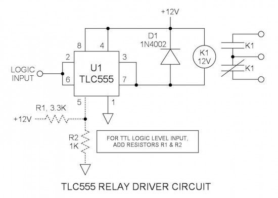
Many integrated circuits possess undocumented features or capabilities. One such example is the TLC555, which can sink a 100mA load down to 1.28V at its output (pin 3). The open-drain transistor reset (pin 7) can also sink 100mA to...
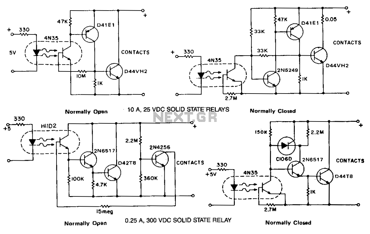
The phototransistor and photodarlington couplers function as direct current relays in saturated switching, handling currents up to 5 mA and 50 mA, respectively. For applications requiring higher currents or voltage capabilities, supplementary devices are necessary to buffer or amplify...
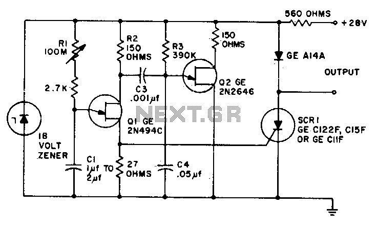
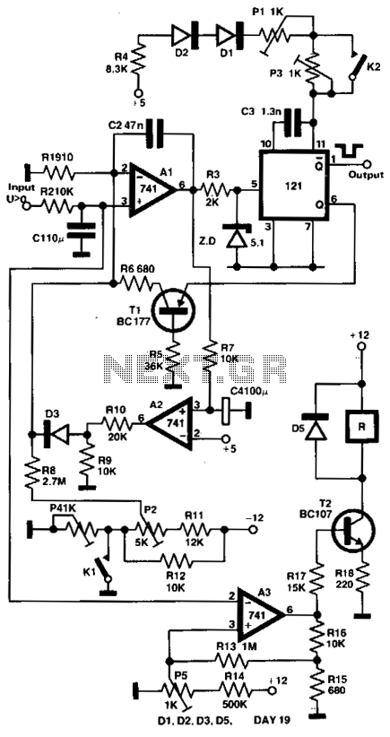
Predictable time delays ranging from 0 milliseconds to over 3 minutes can be achieved without the use of a large electrolytic timing capacitor. Instead, a stable low leakage paper or mylar capacitor is employed, effectively reducing the peak point...
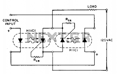
If load current requirements are relatively low (i.e., maximum forward RMS current of 500 mA), an AC solid-state relay can be constructed quite simply by connecting two H11C optically coupled SCRs in a back-to-back configuration as illustrated. The proposed circuit...
The output voltage of a thermocouple is converted into a frequency that is measured by a digital frequency meter. The output signal from the thermocouple is proportional to the temperature difference between the hot junction and a reference thermostat...