
Temperature meter

The TCA965 window discriminator integrated circuit is designed for applications requiring precise temperature monitoring and control through a defined voltage window. The configuration begins with the use of two potentiometers: RV1 and RV2. RV1 is crucial for setting the reference voltage at the center of the window, while RV2 determines the width of the voltage window. This allows the system to effectively respond to temperature fluctuations detected by the thermistor TH1.
The potential divider formed by resistor R1 and thermistor TH1 is essential for establishing a voltage level that reflects the ambient temperature. The choice of R1 is critical; it is selected to ensure that under standard conditions, the output voltage at the divider's junction is half of the supply voltage. This midpoint serves as a reference for the window discriminator's operation. As the temperature changes, the resistance of TH1 varies, leading to a corresponding change in the voltage at the junction. This dynamic input is what the TCA965 monitors to determine if the temperature remains within acceptable limits.
The Schmitt trigger configuration within the IC incorporates a low hysteresis characteristic, which is advantageous for minimizing noise and ensuring stable switching behavior. The output state of the IC will indicate whether the input voltage—derived from the potential divider—is within the defined window or outside of it. If the voltage exceeds the upper threshold or falls below the lower threshold, the IC will activate its output signals.
These output signals are then utilized to drive LEDs, providing a visual indication of the operational state. A current-limiting resistor is included in series with the LEDs to prevent excessive current flow, ensuring the longevity and reliability of the indicator lights. This design not only enhances user interaction through visual feedback but also serves as a critical component in the overall temperature monitoring system, allowing for real-time assessment of environmental conditions.TCA965 window discriminator IC allows the potentiometers RVl and RV2 to set up a window height and window width respectively. Rl and thermistor THl for a potential divider connected across the supply lines. Rl is chosen such that at ambient temperature the voltage at the junction of these two components will be approximately half supply.
As the temperature of the sensor changes, the voltage will change. RVl will set the point which corresponds to the center voltage of a window the width of which is set by RV2 The switching points of the JC feature a Schmitt characteristic with low hysteresis. The outputs of ICl indicate whether the input voltage is within the window or outside by virtue of being either too high or too low. The outputs of ICl drive the LEDs via a current limiting resistor.
Related Circuits
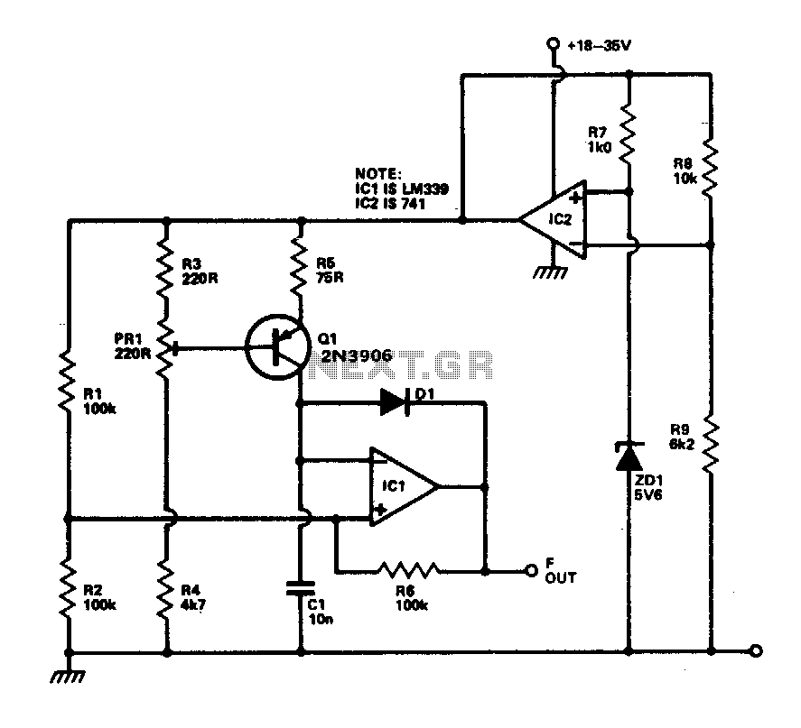
This circuit provides a linear frequency increase of 10 Hz per °C over a temperature range of 0 to 100 °C and can be utilized with logic systems, including microprocessors. The temperature probe Q1, utilizing the Vbe characteristic, changes...
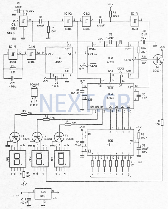
This compact device, designed primarily for modelers, provides instantaneous readings of pulse duration in milliseconds (ms). It can measure servomotor positions, typically ranging from 1 ms to 2 ms, and can also perform repetitive or non-pulsed measurements, such as...
A real-size printout of the PCB is created to verify the dimensions of all components against it. If a component is too large or small to fit its PCB pads, adjustments to the PCB layout can be made, or...
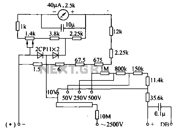
The voltage converter can be configured to switch between AC voltage ranges using a selector switch. The measurement circuit is depicted in the accompanying figure. In this configuration, a shunt resistor is placed in parallel with the header, maintaining...
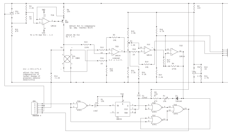
The circuit is powered by the receiver's pack, the current drain is low, especially if compared to drain of servos. U1a VZ2 and Q1 are the current source of the sensor. VZ2 is temperature compensated; use the listed component...
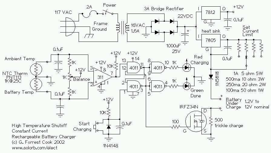
This circuit is designed for a temperature-controlled constant current battery charger, compatible with NiCd, NiMH, and other rechargeable cells. It operates on the principle that most rechargeable batteries exhibit an increase in temperature when they are fully charged. Overcharging...