
Temperature Sensor

The LM35 temperature sensor is a precision device widely used for temperature monitoring applications. It outputs a linear voltage proportional to the temperature in degrees Celsius, making it suitable for interfacing with various electronic systems. The operational amplifier (LM324) in the circuit serves multiple roles, including signal amplification and buffering, ensuring that the A/D converter receives a stable input for accurate digital representation of temperature readings.
The A/D converter (7107) is crucial for converting the analog voltage signal from the LM35 into a digital format that can be displayed on the LED display. The careful selection of components, such as the metal film resistors, ensures minimal drift and high accuracy, which is essential for applications requiring precise temperature measurements.
The temperature-sensitive diode used in the circuit provides an alternative method for temperature measurement, functioning effectively in conjunction with the A/D converter. This configuration allows for cold junction compensation, which is vital in thermocouple applications to maintain accuracy across varying ambient temperatures.
The digital thermometer's ability to operate over a wide range of temperatures, from -55°C to +150°C, showcases its versatility in different environments. The integration of a semiconductor IC sensor (SL590) enhances the circuit's performance by simplifying the conversion process and reducing component count.
Overall, this electronic schematic represents a sophisticated approach to temperature measurement, combining various technologies to achieve high accuracy, stability, and ease of use in diverse applications.The LM35 temperature sensor provides an output of 10 mV/ƒ for every degree Celsius over 0ƒ. At 20ƒ the output voltage is 20 x 10 = 200 mV. The circuit consurnes 60 A. The load resistance should not be less than 5 k ©. A 4- to 20-V supply can be used. (View) The circuit shown in the picture is the digital temperature meter circuit which us es temperature-sensitive diode as the temperature-measurement element. It is mainly made up of the A/D converter 7107, operational amplifier LM324, 3-digit LED display circuit and temperature-sensitive diode and so on. It features high accuracy, good stability, versatility, ease of use and so on. Its temperature measurement range is 0ƒ~100ƒ with accuracy ±1ƒ. The voltage follower, which is made up of the operational amplifier A1, supply power for the A/D converter integrated circuit IC2 and the temperature sampling circuit separately to reduce the interaction between them.
The semiconductor transistor VT1 and R1, R2, R3 supply stable bias current for the temperature-sensitive diode VD1. (View) This circuit`s output voltage Vo`s temeratrue sensitivity is 10mV/ °C. The resistance R is current-limit resistance. The capacitor C is used to improve the stability of the circuit. When the test position and the result-reading position have a far distance, the wire resistance`s voltage drop would cause some extent measuring errors.
(View) The resistance in the cirtuit is metal film one. Itsaccuracy is better than 1% and temperature coefficient TCis less than ±50X10-6/K. The measuring range is from0ƒ to 100ƒ. Current I= 4+T/6. 25. The temperate unit is ƒ and the current unit is mA. The current shows KTY87two-wire current transmitter consisting of Wheatstone bridge with pre-amplifier, current transmitter stage and voltage regulator. (View) The circuit shows the thermocouple input circuit withtwo temperature zones and diode cold junction compensation.
This circuit uses J-type thermocouple as temperature sensor, semiconductor diode Das cold junction temperature compensation to form the relative 0oC of the measurement, to measure the temperature, T1 temperature range is from 0 to 1000oC. The temperature of T2 is equal to the temperature TD of semiconductor diode D. When the measured temperature changes in the range of 0to 1000oC, J-type thermocouple will have a 58mV change.
When the ambient temperature is +25oC, the typical value would be 1. 28mV. Corresponding 0oC transmission current is 4mA, corresponding 1000oC transmission current is 20mA. (View) The temperature difference between two points is often measured in many situations. For example, in water pump fan design and other designs, the impeller shape is always detemined by the temperature difference between the entrance and exit. if the difference is small, it requires high precision phase resolution. Figure 8 shows a high sensitivity temperature measurement circuit with 100mV / ƒ sensitivity. The precision op amp LM308 ouput 10 times of the differential temperature voltage the two temperature sensors measured.
The Op amp output will be 0 by adjust the Rw when the two sensors are in the same temperature. (View) This digital thermometer electrocircuit is composed of SL590, a new semiconductor IC temperature-sensitive sensor and three half digital voltage panel 5GM14433, and it can measure the temperature in the range of -55~15o ƒ. The SL590 make the temperature be a type of current semaphore, which become ratio`s voltage semaphore at Celsius temperature after making the null point displacement by operational amplifier, and sent to the UX input terminal of 5GM14433, then be digital quantity displayed by LED.
The supply is d. c two types, and alternating current supplyed by 220V, also could be supplyed by 4 pieces of 1. 5V batteries. (View) This digital thermometer electrocircuit is composed of SL616, a newsemiconductor IC temperature-sensitive sensor and three half digital voltage panel(DVP 🔗 External reference
Related Circuits
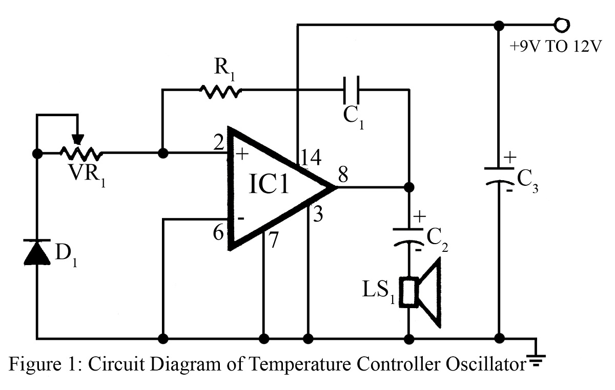
The output frequency or tone of this oscillator circuit varies with the temperature at which the input germanium diode is maintained. The reverse resistance of D1 ranges from 500 ohms to 10 k ohms when the temperature fluctuates between...

The UV TRON flame sensor, manufactured by Hamamatsu Photonics in Japan, is an ultraviolet light detector with a spectral sensitivity range of 185 nm to 260 nm. It is completely insensitive to visible and infrared light, eliminating the need...

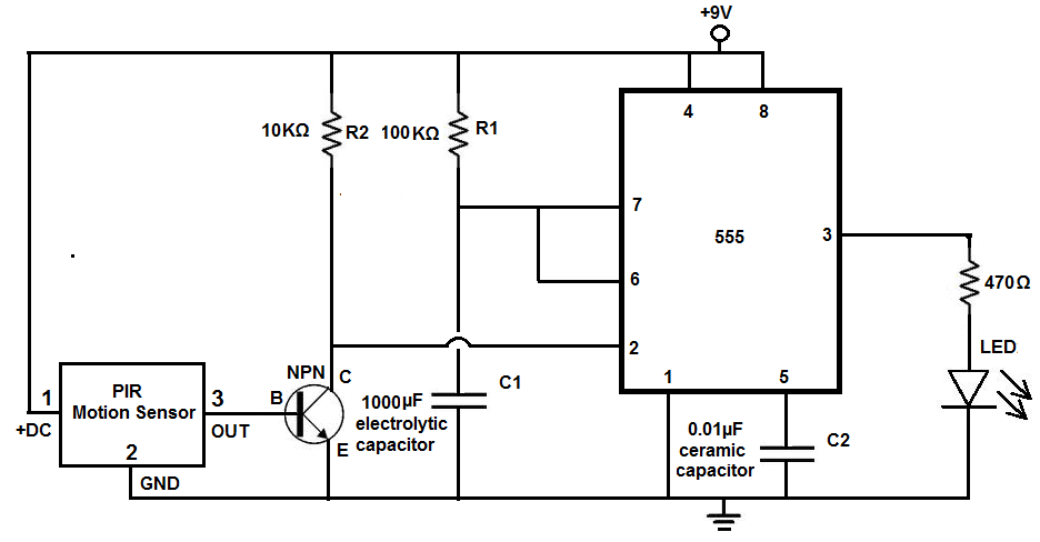
This document outlines a revised version of an LM35-based digital thermometer project previously shared. While it is a straightforward project, it remains popular among beginners learning about microcontrollers. The initial version contained a flaw, as some readers noted that...
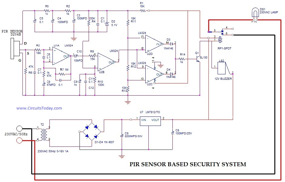
PIR (Passive Infrared Radial) Sensor-Based Security System, circuit diagram, working, applications. The PIR (Passive Infrared) sensor-based security system is designed to detect motion by measuring changes in infrared radiation emitted by objects in its vicinity, particularly warm bodies such as...
Many individuals install motion detectors in their backyards or homes to automatically turn on lights when movement is detected. Motion sensor lights have gained popularity and are increasingly utilized in various settings. Businesses frequently employ them in bathrooms, where...
An affordable electronic device useful for demonstrating electrostatic phenomena. Ahern's instrument serves as an effective substitute for the tonal electrostatic voltmeter. It provides polarity-dependent information about electric charge motion that conventional instruments do not offer. This apparatus is easy...