
Ten-way operation of the dynamic braking circuit

The reel control circuit depicted in Figure 3-142 is designed to facilitate the efficient winding of plastic banding onto a reel while ensuring safety and operational reliability. The coiler mechanism plays a crucial role in this process, as it must manage the tension of the plastic banding material effectively. Given the low tensile strength of the plastic tape, it is imperative to have a system that can quickly halt the motor to prevent any potential damage or mishaps.
The integration of a photoelectric counting device allows for precise monitoring of the amount of tape wound onto the reel. This feature is essential for applications requiring accurate measurements and consistent tape lengths. The system is designed to respond promptly to operational commands. When the stop button (SBz) is pressed, it activates a sequence of events: contact KMi is released, which in turn triggers KM2. This activation engages the electromagnetic clutch Y, facilitating the immediate application of the dynamic braking circuit.
The dynamic braking circuit is a critical component, as it ensures that the motor can stop rapidly, thereby minimizing the risk of the tape being pulled off the reel. The inclusion of a time delay relay (KT) introduces a brief pause between the activation of the brake and the stopping of the motor. This delay, adjustable between 1 and 2 seconds, provides a buffer period that allows for effective deceleration, ensuring that the motor does not experience abrupt halting that could lead to mechanical stress or failure.
In conclusion, the reel control circuit exemplifies a well-engineered solution for managing the winding process of plastic banding, incorporating safety features and real-time monitoring to enhance operational efficiency and reliability. The careful coordination of electrical components ensures that the system can respond effectively to user inputs while maintaining the integrity of the material being processed.Figure 3-142 for the reel control circuit means. Coiler is used to wound with plastic banding (such as grafting with banding tape) of. The length of plastic tape wound on a pla stic reel. Due to the low intensity of plastic tape to avoid plastic belt pulled off, stop the motor when the machine must be quickly stopped. In addition, the length of plastic tape measure wound on a reel, and requires the use of photoelectric count the number of devices.
When stop, press the stop button SBz, contact KMi release, KM2 pull, electromagnetic clutch Y and dynamic braking circuits operate simultaneously, the motor brake quickly shut down. Using the time delay relay KT (1 ~ 2s) aimed at ensuring that there is sufficient braking time. In fact, several motor is decelerated to stop almost instantaneously. Figure, the contact K, when the photoelectric counter preparations do count
Related Circuits
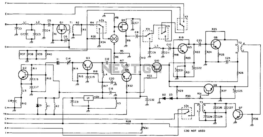
This 49-MHz FM transmitter comprises an audio amplifier, a low-pass filter, three RF stages, and a regulated DC power supply. The output power is approximately 16 mW into a 50-ohm load. This transmitter is suitable for various 49-MHz applications,...
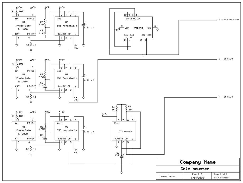
The next counter section operates similarly but is designed to count four quarters, single $1 coins (loonies), and single $2 coins (toonies). The circuit for the toonies is configured. The circuit for the counter section includes a digital counting mechanism...

The Pyro Propeller Clock POV schematic is relatively straightforward. It consists of three primary components: the power supply utilizing a 7805 voltage regulator, the LED output control managed by a PIC18F252 microcontroller and a 74LS373 latch, and the 'home'...
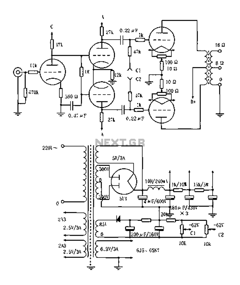
The Elliot 2A3PP line amplifier is a straightforward design, emphasizing the quality of the output transformer. It utilizes a 3KPP output transformer with a fixed bias of 62V, delivering an output power of 15W. The 2A3PP is well-suited for...
This document explains how to connect lights so that they flash when the phone rings. This setup is particularly beneficial in noisy environments, such as workshops, where it is challenging to hear the phone ringing. The ring detection component...
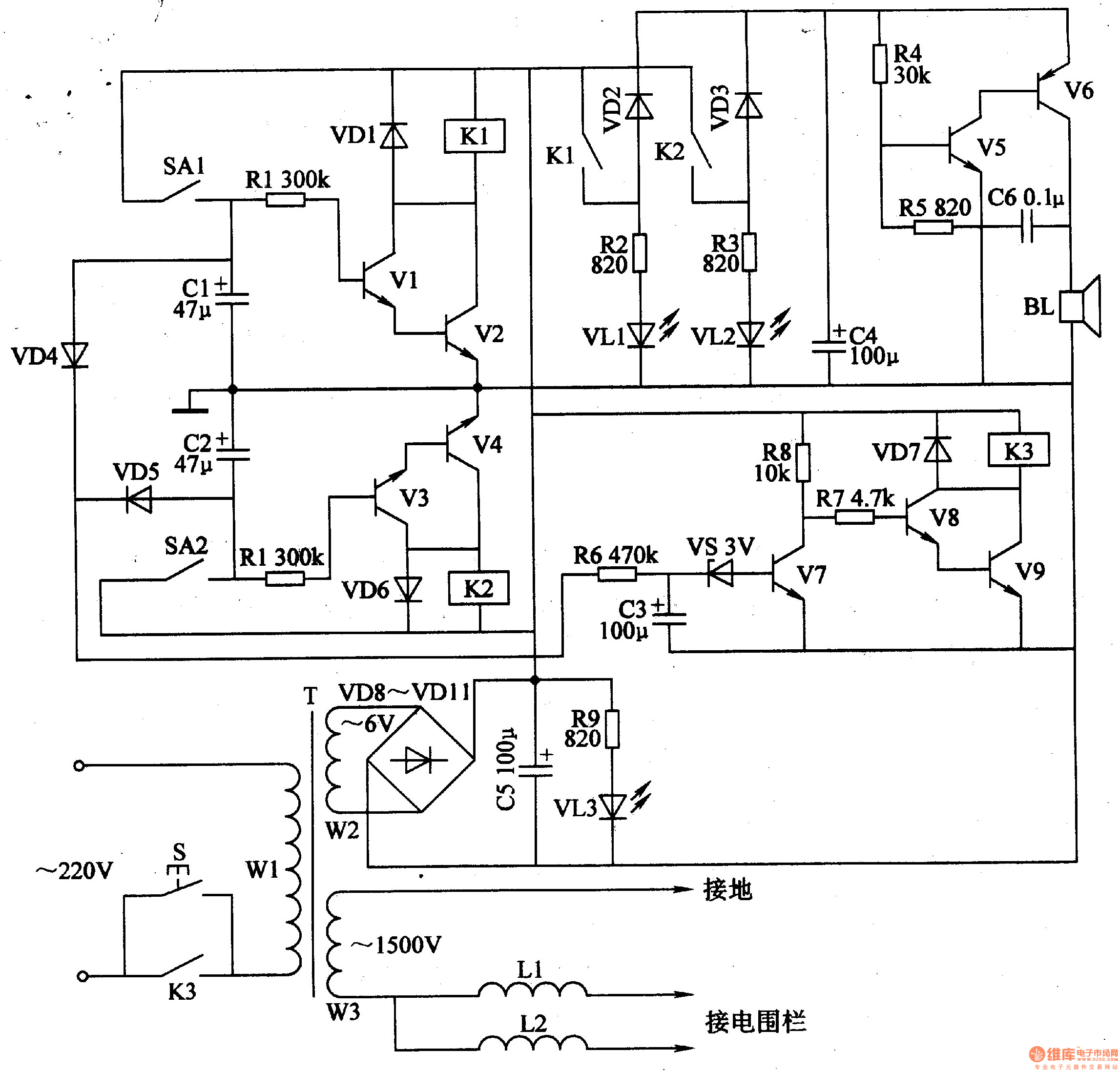
The electric fence control circuit includes a +6 V power supply circuit, a high-voltage output circuit, a trigger control circuit, an alarm circuit, and a protection circuit. The +6 V power supply circuit consists of a power control button...