
tesla coil

The circuit design incorporates a 555 timer configured in astable mode, which generates a square wave output that drives the ignition coil. The photocoupler serves as an isolation barrier, ensuring that high voltage spikes do not affect the low voltage control circuitry. The choice of the photocoupler is flexible, allowing for various models that meet the required specifications.
The ignition coil is connected to the primary side of the Tesla coil circuit, where it transforms the low voltage input into high voltage output. The spark gap is positioned in parallel with the primary coil and is responsible for creating a discharge path for the energy stored in the capacitor. As the capacitor charges, once it reaches a certain voltage, it discharges through the spark gap, generating a high-voltage pulse that excites the secondary coil of the Tesla coil, producing electrical arcs.
For optimal performance, the circuit may require tuning of the capacitor and resistor values in the timing circuit to achieve the desired frequency and arc length. A variable resistor could be integrated to allow for real-time adjustments during operation. The optional audio input provides an interesting feature, enabling sound modulation through the Tesla coil, although care should be taken to avoid damage to sensitive audio equipment.
The isolation of the power sources is critical in preventing ground loops and ensuring the safety of the entire system. The schematic should clearly indicate all connections, including power supply inputs, output connections to the ignition coil, and the layout of the components for clarity. Proper heat dissipation measures should also be considered for components that may generate significant heat during operation. Overall, the design emphasizes safety, reliability, and flexibility for experimentation with various component values and configurations.This circuit was designed to not fry the 555 timer, this is because I noticed that having the ignition coil share a high voltage contact with a power connector made somewhat high voltages go back and into the 555 timer, thus frying it (I went through about 7 timers before I finally got this to work). So after desoldering a few unused boards, I fou nd out that most of the IC`s I removed were photocouplers and I thought that they could be used to isolate the frequency signal appart from the driver that connects to the ignition coil. In a way the photocoupler acted like a relay. For the photocoupler it does not have to be the cosmo 1010, I just used that one because that was the smallest photocoupler that I removed from the board.
You can play around with the capacitor and resistor values to see what they do, but I found that this combination gives some of the largest arcs from the igntion coil. The ignition coil is not portrayed as connected to the driver circuit, but it is shown clearly where to connect in the schematic of the tesla coil itself.
It is also essential that the 6 volt power source is separate from the 12 volt one, that is why there`s a photocoupler, to completely isolate it. You can see that there is an "audio in" port on pin 5 of the 555 timer, that is optional, but in order to use it, you will have to change the capacitor from a 0.
47uF electrolytic to a 0. 1uF ceramic capacitor (it`s the one with the number 104); all you have to do is connect the output of the audio device to this and connect the common wire to the negative on the 6 volt side, but try not to use anything expensive as I`ve been using a cheap CD player and it acts a bit weird now from being connected, so try not to use your $200 ipod touch or anything like that. The picture of a physical circuit is what the driver circuit looks like, and beside it is the transistor.
The first circuit is the one I used, a basic spark gap Tesla Coil with no additional safety features or regulators or anything. The circuit is wired in a way that you don`t need to have a grounding connection at the base of the secondary, it`s probably recomended but will make things harder and will pose a threat to any of your electronics that are plugged in.
The circuit in the middle is the most basic schematic of a solid state Tesla coil taken off electronsbefree, it is an off-line Tesla coil. I wanted to make one of these, but there isn`t very much information on the internet about this one, and it also involves components that are somewhat pricey and that I don`t currently have access to like IGBT`s and high power MOSFET`s.
The last circuit is a super simple solid state Tesla coil, it must be the most basic one I have ever seen, I think the owner of this image could be found here. I also wanted to make this one, but I don`t have the resources to buy a nice high power MOSFET and the IXYDD414 chip.
The last picture is what my setup looks like. But I got my Tesla coil pretty solid state-ish because of the driver and being able to modulate the frequency with audio. Ignition Coil: Probably the most necesary component in a non-sstc type Tesla coil, but it doesn`t have to be an ignition coil, just as long as it is something that can make a couple thousand volts.
This is the component that supplies the high voltage that is necesarry to drive the unit. If you`ve ever seen or used an ignition coil, you know that there is only 3 connections, which is why I had to design that isolated driver circuit so you don`t get inductive kickback mixed with high voltage signals. Spark Gap: This component is one of the main timing mechanisms. This controls when the capacitor discharges across the primary coil. A drawback of this component is that it creates a lot of light, like an arc lamp. Another drawback is that it is incredibly loud, so this complicated some things when it came to playing music off this coil.
To make this one, I just used 🔗 External reference
Related Circuits
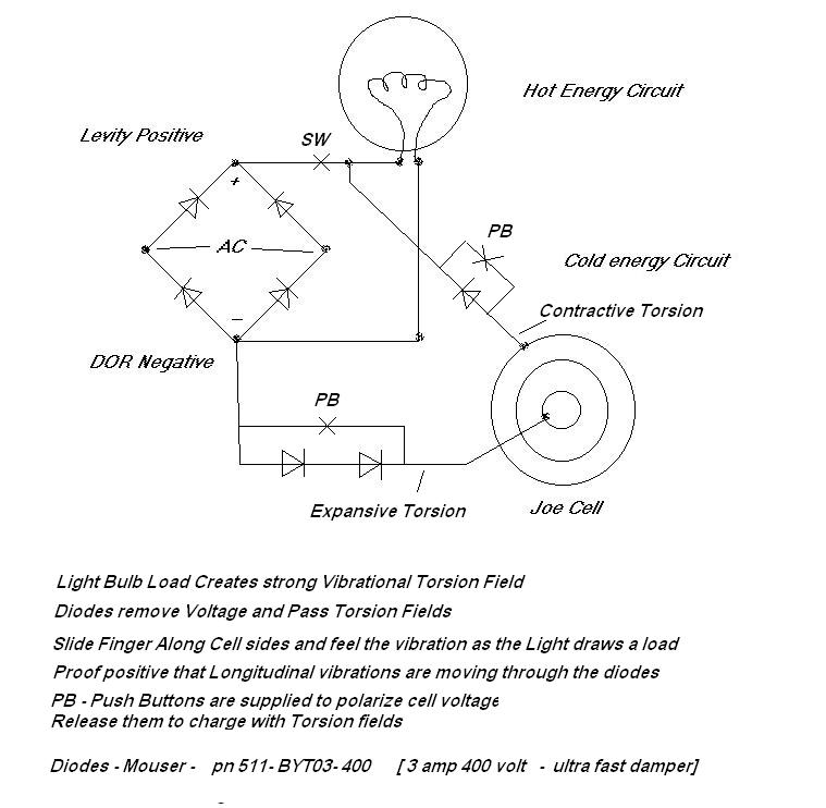
The concept of quadrature involves three manipulable forces rather than the two traditionally considered in electromagnetism. The electric field exhibits both positive and negative voltages, while the magnetic field consists of north and south poles. Additionally, the tempic field...
This crystal set has been designed to incorporate features from previous radio models. The #62 radio merges the single-piece design of the #48 set with the dual detector functionality of more recent models. It utilizes a dual honeycomb coil...

This coil gun design utilizes arbitrary on/off times that are calculated based on the basic equations of motion, rather than chosen randomly. The coils do not activate at uniform intervals; the first coil remains energized for the longest duration...
The Tesla coil described here can generate 25,000 V. Although the output current is low, caution is essential. The primary component is a flyback transformer sourced from a discarded television. A new primary winding is required. Begin by winding...
This area illustrates the construction and testing of a new half-wave (dual) Tesla coil. This type of coil features two secondaries driven by a single tank circuit. The design presented is a small and relatively inefficient dual coil constructed...

When operated through a spark gap, does a Tesla coil always operate at a quarter wave, half wave, or a multiple of a whole wave, resulting in 2*n maximums? Are there sources related to creating standing waves and the...