
The 146.460 MHz Repeater

The radio telephone integrator project represents a significant advancement in amateur radio technology, showcasing the integration of traditional radio frequencies with telecommunication functions. The system's full-duplex capability allows simultaneous transmission and reception, a critical feature for effective communication in radio systems. The choice of 29 MHz and 158 MHz frequencies aligns with common amateur radio bands, facilitating compatibility with existing equipment and enhancing operational flexibility.
The design utilizes components sourced from the ARRL handbook, which provides valuable circuit designs and guidelines for amateur radio enthusiasts. The implementation of touch-tone command functionality enables users to interact with the system effortlessly, enhancing usability while maintaining the integrity of radio communications. The incorporation of a commercial VHF radio as the transmitter and a ham radio as the receiver exemplifies the hybrid approach often found in amateur radio setups, where both commercial and home-built components coexist to achieve desired performance.
The power amplifier upgrade to a 95-watt output represents a crucial enhancement, significantly improving the system's range and overall effectiveness. This upgrade, along with the establishment of a network of full-duplex systems, illustrates the collaborative spirit of amateur radio operators who share resources and knowledge to expand communication capabilities.
The evolution of the ham station, marked by various modifications and upgrades, reflects the ongoing nature of experimentation and learning in the field of electronics. The successful operation of the homemade controller for over 15 years without failure highlights the reliability of well-designed, home-built equipment in amateur radio applications. This project not only serves as a testament to the individual's dedication to the craft but also contributes to the broader community of amateur radio enthusiasts who value innovation, collaboration, and technical skill.Construction of a radio telephone integrator and created my first radio phone / repeater. I had been playing with electronics and radios since that first receiver I had built back in 1973. With that simple receiver and a random wire antenna I had discovered the world of SWL and Amateur radio. Now with Leo`s inspiration I assembled the components for a full duplex radio telephone system using 29 MHz for my input frequency and 158 MHz for my output. This simple system which used circuits found in the ARRL handbook enabled the operator to send touch tone command from a radio system in his or her car back to the base station and access the land line to make and receive phone calls. In these first few photos above you can see Leo`s hand written system schematics for the radio phone integrator.
In the next three photos you can see my system with the commercial VHF radio which was the transmitter and the ham radio used as the receiver. In the photo to the left I was an old VHF radio running about 15 to 20 watts. The photo to the right shows the system after an upgrade with a %100 duty cycle VHF radio and power amplifier running about 95 watts.
With this initial system Leo and I had good radio phone coverage all around northern Rhode Island and into parts or southern Massachusetts. As we developed our little "network" we each ran a full duplex system and shared each others nodes dramatically increasing our range.
We both used the same system output frequency with different input frequencies and the only real trick was to figure out just who`s phone was ringing when one of the systems would activate! These next four photos above show my ham station as it grew and evolved over the next few years. Most of the items in my shack were kit`s, I built the HK-232 packet radio controller and the Code-Star CW Decoder.
All the radios received modification / repairs / upgrades and it is obvious that the system controller was a "home-brew" device, there are a lot of folks that build repeaters but not many that can say they scratch built the controller on perf-board! This first controller was in 7x24 service for more than 15 years and never had a component failure. I still have it today but have salvaged it for parts when building my subsequent "home brew" repeater controllers.
These last two photos are just to remind me how young I was 20 years ago when this obsession with repeaters began. Sandy was right there next two me typing away on the packet radio system. (I think she was sending mail on Syl N1DKF`s PBBS at the time) Eventually I abandoned the radio telephone system but I continued to upgrade and used that original controller on several amateur radio projects.
If you look closely at the various photos you can see that the system controller only had two LED`s / switches originally, now with a third switch that gave the system additional "repeater" functions including a CW IDer, it became my first 2 meter repeater controller. 🔗 External reference
Related Circuits

The only adjustments that require close attention are input, output, and neutralization. The 150-pF capacitor in the input line compensates for impedance mismatch. The tuning process is aimed at achieving maximum signal transfer from the exciter to the final...
This antenna tuning unit (ATU) allows half-wavelength or longer wire antennas to be matched to the 50-ohm antenna input of 27-MHz Citizens Band (CB) radios. The ATU is particularly useful in situations where a wire antenna is less visually...

This project involves a Regenerative Receiver designed for the 80-meter Amateur band, with the capability to tune from approximately 3 MHz to 10 MHz, suitable for Shortwave listeners. It shares a design lineage with the previously created "40-Meter Tweeter."...
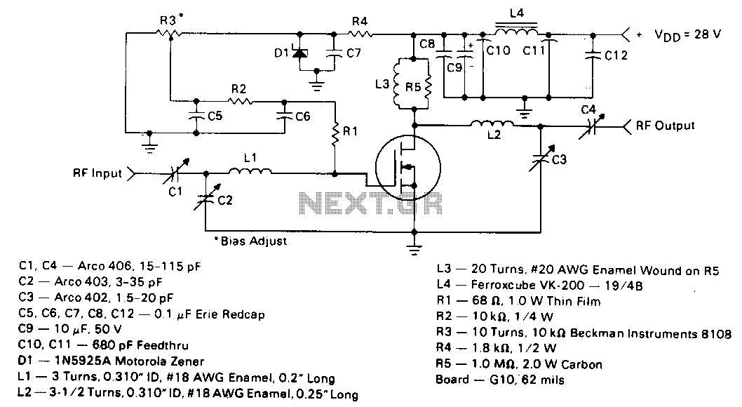
This circuit employs the MRF123 TMOS power FET. The MRF134 is a high-gain FET that may exhibit instability at both VHF and UHF frequencies. A 68-ohm input loading resistor has been used to improve stability. This amplifier achieves a...

Intercom walkie-talkies represent an advanced application of crystal oscillators for voice transmission. Utilizing a crystal-locked oscillator for voice transmission is complex due to the oscillator's fixed frequency, which is challenging to modulate. The primary method for achieving this involves...
The MK50398 is one modern decimal counter up/down of six tens, with control of screen LED of seven segments and flip-flop of storage. Counter it can measure additive and abstractively. The IC MK50398 is ideal for manufacture frequency counter...