
The 4Q2 DC Motor Speed Controller Circuit and Datasheet

The 4Q2 DC Motor Speed Controller serves as a versatile solution for managing the speed and torque of DC motors, particularly suited for applications requiring high efficiency and precise control. The circuit is designed to accommodate both shunt-wound and permanent magnet motors, making it applicable in various industrial and commercial settings.
The controller operates on a nominal voltage of 180V, which is a common rating for many industrial DC motors. The inclusion of isolated control circuits is a critical feature that enhances safety and reliability by preventing interference between the control signals and the power circuits. This isolation helps to protect sensitive components from voltage spikes and noise generated during motor operation.
The armature voltage control is achieved through a closed-loop feedback system that adjusts the voltage supplied to the motor based on the desired speed setpoint. This is typically implemented using pulse-width modulation (PWM) techniques, which allow for fine-tuning of the motor speed while maintaining efficiency. The tachogenerator feedback mode provides real-time speed information to the controller, enabling it to make necessary adjustments to maintain consistent performance under varying load conditions.
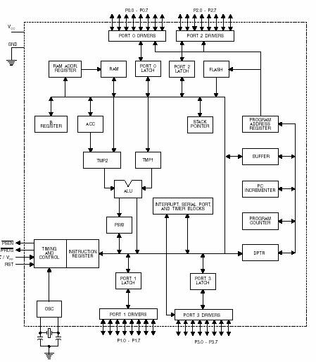
The design of the 4Q2 controller also emphasizes ease of integration into existing systems. The block diagram illustrates the key components, including the power stage, control logic, feedback loops, and user interfaces. Each of these elements plays a vital role in ensuring that the motor operates within its specified parameters, thereby extending its lifespan and improving overall operational efficiency.
In conclusion, the 4Q2 DC Motor Speed Controller is a sophisticated device that combines robust design with advanced control methodologies, making it an essential tool for applications that demand precise motor management and high performance. For detailed specifications and operational guidelines, the full datasheet in PDF format should be consulted.This is the figure of4Q2 DC Motor Speed Controller Circuit Block Diagramwhich is designed for full control of conventional shunt wound and permanent magnet motors up to 75kW capacity, according to the datasheet. This type ofDC motor speed controlleris suitable for operation with 180V motors and incorporates isolated control circuits for armature v
oltage and tachogenerator feedback modes. For complete explanation about the4Q2 DC Motor Speed Controller Circuit and Datasheet, you may find it here in full pdf filetype: 🔗 External reference
Related Circuits
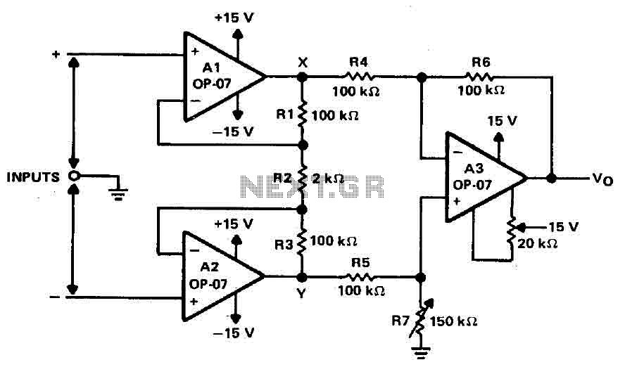
Operational amplifiers A1 and A2 are connected in a non-inverting configuration to form amplifier A3. The operational amplifier A3 can be classified as a subtractor circuit that converts the differential signal between the floating points X and Y into...
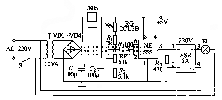
The NE555 time base circuit with an AC solid-state relay (SSR) can function as an automatic light switch circuit. The circuit diagram illustrates that during the day, the incandescent light is turned off due to the influence of the...
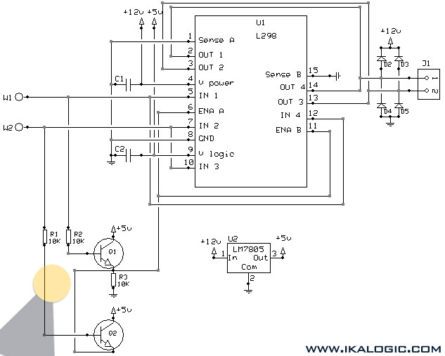
This implementation utilizes the L298 integrated circuit to drive motors and inductive loads with a continuous current capacity of up to 4A. The L298 consists of two independent channels, each capable of driving loads of up to 2A. By...
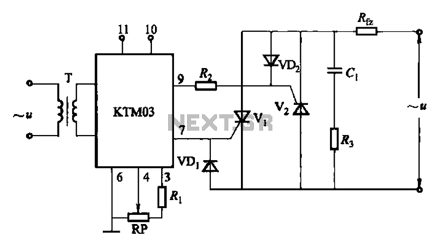
Adjustment potentiometer RP can modify the conduction angle of thyristor Vl, vz, thus altering the voltage applied across the load Rfz. The adjustment potentiometer (RP) serves a critical role in controlling the conduction angle of the thyristors Vl and vz within...
A microcontroller (MCU) is a compact computer integrated into a single circuit, comprising a relatively simple CPU along with supporting functions such as crystal oscillators, timers, sensors, and serial and analog input/output (I/O). Microcontrollers are designed for small-scale applications,...
The LM1036 is a DC controlled tone (bass/treble), volume and balance circuit for stereo applications in car radio, TV and audio systems. An additional control input allows loudness compensation to be simply effected. Four control inputs provide control of...