
The AA8V Twinplex Regenerative Receiver

The regenerative receiver circuit, particularly in the context of the Twinplex design, demonstrates a unique interplay between components that facilitate signal amplification and tuning. The antenna coupling capacitor serves as the initial interface, allowing for adjustable coupling that is crucial for the receiver's sensitivity. The parallel resonant circuit formed by L1 and the associated capacitors plays a pivotal role in isolating the desired frequency while filtering out unwanted signals. The integration of the tickler coil into the circuit introduces a feedback mechanism that is central to the regenerative process, enabling significant amplification. The careful design of the grid biasing and decoupling circuits ensures that the receiver maintains stability and selectivity, preventing overload while allowing for effective audio signal processing. This intricate balance of components and their interactions is what enables the regenerative receiver to function effectively, making it a notable choice in specific radio applications.The antenna coupling capacitor is a critical component in a regenerative receiver without an RF stage, like the Twinplex. In such a receiver, the antenna is an integral part of the regenerative detector, and for proper operation the coupling to the antenna must be easily adjustable.
Increasing the capacitance increases the coupling and vise versa. After passing through the coupling capacitor, the signal is applied to a parallel resonant circuit consisting of L1 and the bandset and bandspread capacitors. The resonant circuit shorts to ground all signals except that to which the circuit is tuned (resonant frequency.
) The resonant frequency is determined by the inductance of L1, which can be changed by switching coils, and the settings of the bandset and bandspread capacitors. The bandset capacitor is used to set the portion of the band you wish to tune, and the bandspread is then used for the fine tuning.
Because the antenna is part of the detector circuit, changing the antenna or the antenna coupling also affects the frequency to which the receiver is tuned. This is one of the shortcomings of this type of circuit. For more information on this, see my page on How to Operate a Regenerative Receiver. The output of the resonant circuit is coupled to the grid of the first triode through a 100 pf capacitor.
The grid and cathode of the triode function as a diode and rectify the signal, much as the crystal diode does in a crystal radio. The rectifying action puts a negative charge on the grid, and this charge would build up and eventually make the grid so negative that the tube would be cut off.
To prevent this, the 2. 2 Megohm resistor bleeds some of the charge off, leaving a small negative voltage (grid bias) on the grid. The grid bias helps to prevent the tube from loading the tuned circuit, which would lower the selectivity.
The tickler coil L2 is the part that distinguishes a regenerative detector from all others. The amplified signal in the plate of the tube passes through the tickler coil, which is wound in close proximity to the tuning coil L1. The two coils form a transformer, and some of the amplified signal in the plate circuit is fed back in phase to the input circuit.
This positive feedback, or regeneration, gives the detector its name and takes place over and over again, amplifying the signal many times over that which would normally occur. This allows a huge amount of amplification to take place in a single stage. The tickler coil must be connected with the proper polarity, otherwise the feedback reduces, rather than increases, the gain.
A common mistake in constructing a regenerative receiver is to connect the tickler coil backwards. If your receiver does not want to regenerate properly, try reversing the connections to the tickler coil. Too much regeneration is as bad as too little, so the regeneration must be adjustable. There are several ways to do this, but in the Twinplex the plate voltage of the detector is varied to control the regeneration.
The regeneration control is a potentiometer connected between B+ and ground. Changing the position of the wiper changes the plate voltage of the detector. Since the wiper can generate some noise, and since the detector can greatly amplify the noise, a 0. 22 uf capacitor is connected between the wiper and ground to short circuit the noise to ground. The signal in the plate circuit consists of the amplified RF signal along with the detected audio. The plate decoupling circuit allows the audio to pass through, while blocking the RF. The reactance of the 470 pf capacitor is very low at RF, effectively grounding one end of the tickler coil for RF and completing the plate circuit for RF. Without this capacitor, the receiver will not regenerate. At the same time, the reactance of the capacitor is much higher at audio frequencies, keeping them from flowing to ground.
On the other hand, the reactance of the 2. 5 mH RF c 🔗 External reference
Related Circuits
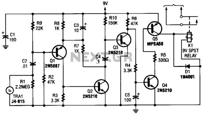
A GC Electronics P/N J4-815 transducer is utilized to receive 40-kHz acoustic remote-control signals. The receiver activates a relay to control another circuit. The GC Electronics P/N J4-815 transducer is designed specifically for the reception of 40-kHz acoustic signals, which...
The Command Transmitter-Receiver (A3023) is designed to test the command receiver proposed for the Implantable Sensor with Lamp (ISL) in the conceptual design phase. The A3023 consists of two primary components: the Command Transmitter section, which features a 146-MHz...
This project will explain how you can build a receiver for 35MHz. The receiver is based on the FM receiver circuit MC3371, and the frequency is PLL controlled with LMX2306 circuit. In this project, a radio receiver for RC...
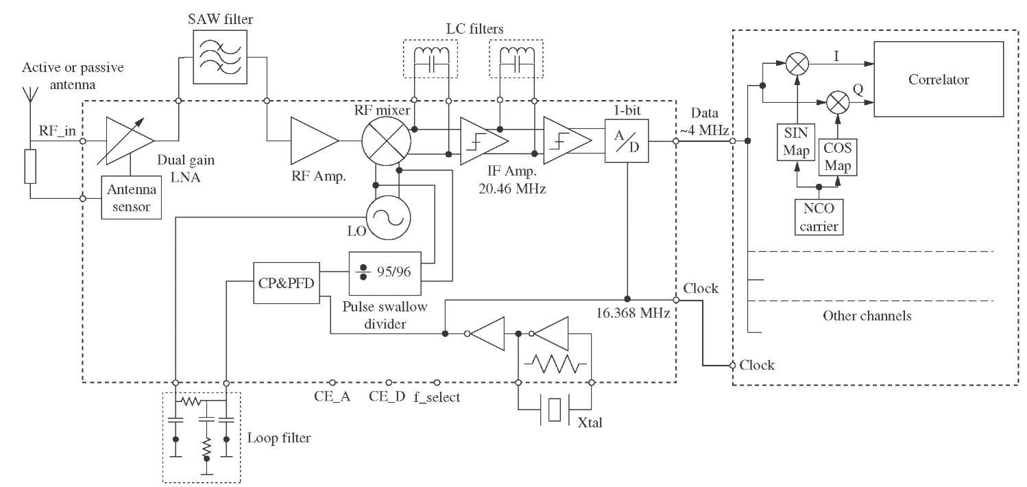
This topic will detail the design of each block of the radio frequency (RF) front-end, taking into account the technical requirements outlined previously. The design aims to meet specific specifications. The RF front-end is a critical component in communication systems,...
This set of two circuits forms the basis for a very simple light wave transmitter. A LASER beam is modulated and then aimed at a receiver that demodulates the signal and then presents the information (voice, data, etc.). The...
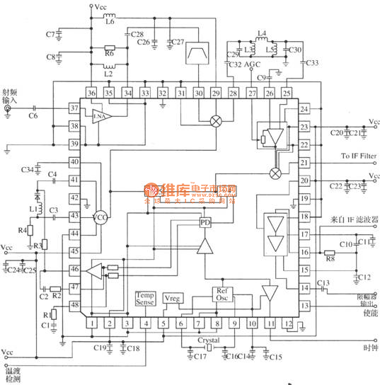
MRFICl505R2 is a 1.575GHz GPS downconverter chip. It integrates a mixer, VCO, PLL, crystal oscillator, A/D converter, loop filter, and other circuits. The MRFICl505R2 IF output frequency is 4.1MHz, with a typical conversion gain of 105dB, an operating voltage...