
The electric current of mode control of the average current measures the circuit design of the voltage transformer

In the context of designing a circuit for mode control of average current with a focus on power factor correction, several critical components and parameters must be considered. The primary goal is to ensure that the circuit operates efficiently while preventing saturation of the voltage transformer. The selection of voltage transformers with appropriate specifications is crucial; they must be capable of handling the required current levels and frequency ranges without compromising performance.
The schematic should include the key elements such as the voltage transformers, current sensing resistors, and control circuitry. The voltage transformers should be positioned to accurately measure the electric current flowing through the system, and their output should be fed into a control loop that adjusts the switching frequency and duty cycle of the converter. This control loop will utilize feedback from the current sensing resistors to maintain the desired average current levels.
Additionally, the design must incorporate protective features to mitigate the risk of saturation. This can be achieved through careful selection of the reset resistor (R1) and ensuring that the magnetizing current is adequately controlled. The calculations for R1 must take into account the expected peak currents and the desired reduction factor, ensuring that the transformer operates within safe limits.
The timing of the switching elements, particularly Q1, should be synchronized with the current waveform to optimize performance. The design should also consider the thermal management of the components, as excessive heat can lead to failure and decreased efficiency.
In summary, the circuit design for mode control of average current in a power factor correction topology requires meticulous attention to component selection, parameter calculations, and timing synchronization to ensure reliable and efficient operation while preventing saturation of the voltage transformers.Mode control of the average current CMC Require it in order to control the total waveform of electric current of rebuild of cycle. This text recommend, choose concrete the intersection of voltage transformer and required some step for you, and how design one can satisfy terminal to employ against voltage transformer saturation demand circuit.
Themodel that we used is the power factor correction PFC Topological. It is analyzed that the lieutenant general uses a kind of commercial electric current to measure the voltage transformer, is used for confirming the required parameter, understand how to utilize this kind of information to design a kind of circuit very against saturation. It means the power pulse open to reach PFC average CMC required electric current signal rebuild goal Time Electric current during this time and idle the intersection of energy and recover time close Time The electric current during this time, must include in electric current signals produced.
Under heavy-duty PFC, the loss of the sensor system of the resistance is extremely high, so need to use the voltage transformer of the electric current. In analyzing, we design paying proving to this kind of required electric current voltage transformers in PFC circuit, because it is stricter to compare canonial forward converter its requirement.
The schematic diagram of the power level of a power factor control converter of Fig. , including explaining this electric current measures the required detailed electric current of circuit design and measures the voltage transformer parameter Table 1 has listed the concrete details of two electric current voltage transformers used for discerning correctly this kind of converter uses. IinLpk electric current shows the required electric current voltage transformer has switching frequency of about 20 amperes of primary current handling capacity and 100 kHz.
One has primary current handling capacity and 50 kHz PA 1005. 100 electric current voltage transformer to 1 MHz frequency domain of 20 amperes, can meet the requirement for this kind of design. Suppose the converter works under maximum load and minimum input voltage, can calculate and receive the voltage of the secondary winding.
This total voltage is by the voltage of the current sensing resistor Rsense according to defining as 1 volt, diode voltage Define as 0. 7 volts And the voltage of the resistance VRwinding of coil makes up, its algorithmic method equation 3 as follows : At this moment, you need to confirm this voltage transformer has not presented the saturation.
Utilize and derive the resulting value, its calculation equation equation 7 as follows : Because the flux density of this kind of disposition is got under the extreme condition, it less than being apt to produce lateral half of flux of the saturation, so is only closing Time can be reduced sharply, then allow the magnetizing current to increase nearly three fold at this moment. In order to prevent the voltage transformer Move towards Saturation, you need to have one to bend over the total mark second at time when Q1 close.
In this way, can be here Open The time equilibrium bends over the total mark second. Through putting a resistor R1 Called resetting the resistor, Can achieve this purpose, open like this The formative magnetizing current will be here during this time Close Force and reset resistor R1 in this during this time China forms voltage of a volt. Please remember, the voltage of this resistor will be reduced and dropped with the magnetizing current.
If you want to know the value of R1, it is 2 to set up the magnetizing current of the crest value * DImagpk, then design the circuit, is so opening Select to reduce the magnetizing current to 0. 5 with resistor during this time * DImagpk. So can guarantee the crest current is lower than 2 * DImagpk can work normally too hour. Will magnetize the inductive 🔗 External reference
Related Circuits
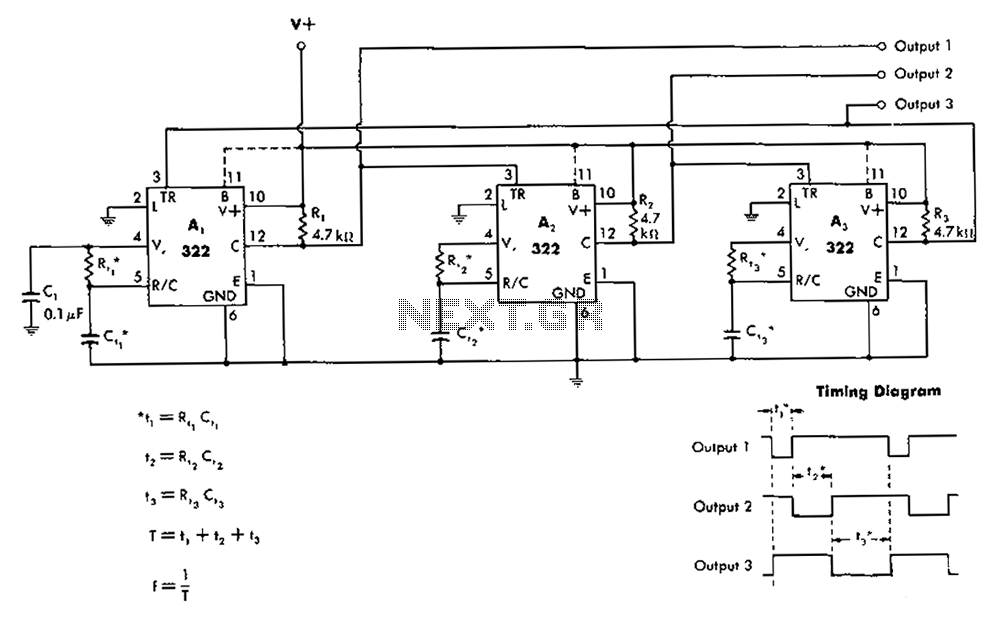
The 322 monostable multivibrator is configured in a cross-connected manner. When operating under non-steady state conditions with the oscillator Unicom, it generates a continuous timing cycle, as illustrated in the accompanying figure. T represents the total time period of...
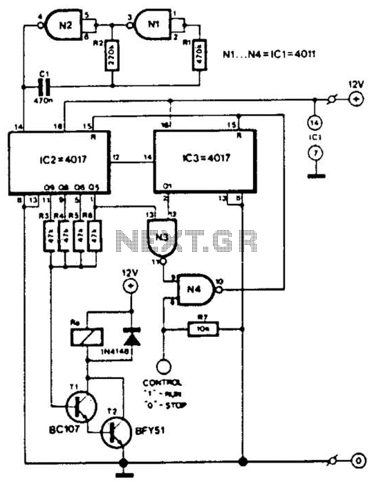
This circuit is designed for a small private telephone installation. The ringing tone sequence consists of 400 ms on, 200 ms off, 400 ms on, and 2 ms off. In the accompanying diagram, N1 and N2 create an oscillator...
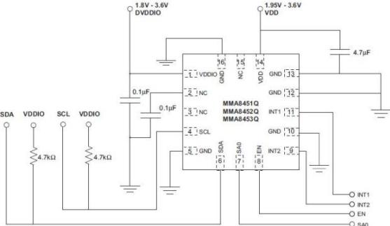
The task involved implementing and programming all hardware devices to make data accessible to the receiver program running on a PC. This included configuring all Prospeckz devices and establishing protocols for radio transmission communication back to the PC. Additionally,...
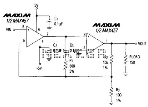
A composite amplifier can be constructed that offers high gain, wide bandwidth, and good DC accuracy by cascading the sections of a dual video amplifier and incorporating two suitable phase compensation components. The operational amplifier drives a 150-ohm load...
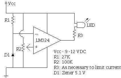
An ECU must have a way to monitor battery voltage. Here is a simple op-amp based circuit which will illuminate the LED when the battery voltage drops to a certain level. The turn-on point is set with R2. You...
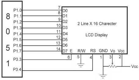
The link shows how to interface Alphanumeric LCD to 8051 Microcontroller. Liquid Crystal Display also called as LCD is very helpful in providing user interface as well as for debugging purpose. The most common type of LCD controller is...