
The motorcycle anti-theft alarm (3)
")
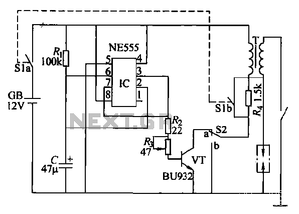
The motorcycle anti-theft alarm system is designed to enhance the security of motorcycles by detecting unauthorized movement. The core component of this system is the 555 timer IC, which operates in a monostable mode to generate a time-delayed output signal. This signal is used to trigger the alarm when the motorcycle is tilted or lifted, indicating potential theft.
The trigger circuit typically includes a tilt sensor or a vibration sensor, which detects the motion of the motorcycle. When the sensor is activated by vertical movement, it sends a signal to the 555 timer IC. The timer is configured to produce a high output for a predetermined duration, which can be adjusted based on the user's preference. This output activates the alarm circuit, which may consist of a loudspeaker or siren to alert nearby individuals of the theft attempt.
The alarm circuit can also include additional features such as LED indicators to visually signal the alarm status or a relay to control other security devices. Power supply considerations are crucial; the circuit can be powered by the motorcycle's battery, ensuring that it remains operational even when the motorcycle is parked.
In summary, the motorcycle anti-theft alarm circuit using a 555 timer is an effective solution for enhancing motorcycle security. Its simple design allows for easy installation and customization, making it accessible for a wide range of users looking to protect their vehicles from theft.The motorcycle anti-theft alarm which uses the 555 time-base integrated circuit is introduced in this article, and it can send out the alarm when the thief is moving the motorcycle vertically. The principle of the circuit The motorcycle anti-theft alarm circuit is composed of the trigger circuit and the alarm circuit, as the figure 7-85 shows.The trigger..
🔗 External reference
Related Circuits

This design outlines a fire alarm circuit that utilizes a light-dependent resistor (LDR) and a lamp to detect fire. The alarm is activated by sensing the smoke produced during a fire. When smoke is present, it obstructs light from...
This paragraph describes an easy car alarm circuit that utilizes fewer components and is simple to produce. The circuit consists of an automobile anti-theft alarm system based on the NE555 timer, a power switch (VT), and a switch (S2),...
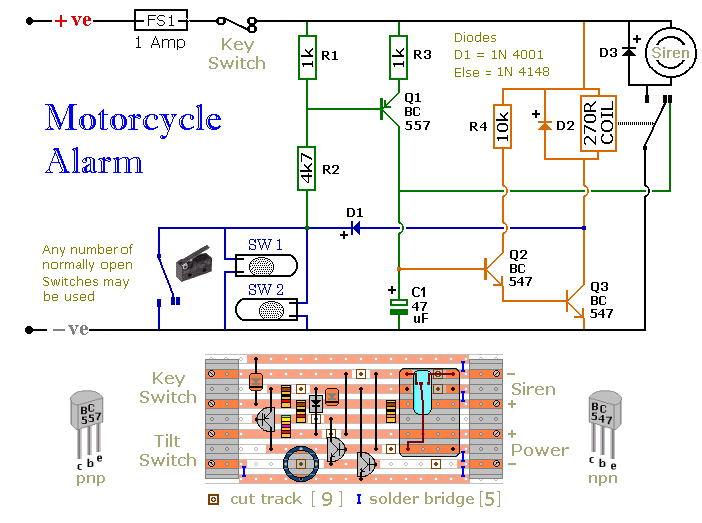
The circuit board and switches require protection from environmental factors, as moisture or condensation can lead to malfunctions. The board is compact without its terminal blocks. It is advisable to select a siren that has sufficient internal space for...
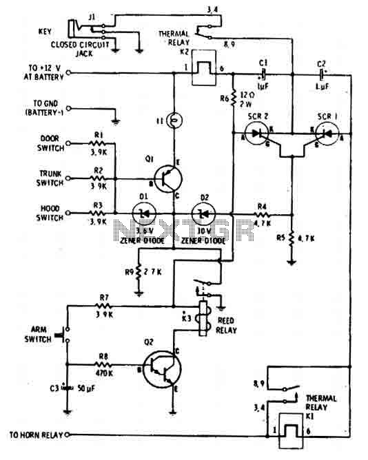
The car alarm is a straightforward circuit with fundamental features that monitor all entry points of the vehicle, such as doors, using switches. It operates with a single switch (the arm switch) that allows the circuit to remain inactive...

When this alarm is activated, its siren will sound once for up to 20 minutes. After this period, it will switch off and remain off. The basic circuit features a single zone with independently adjustable exit and entry delays,...
This circuit utilizes a 555 timer integrated circuit (IC) to function as an alarm system designed to deter theft of personal belongings, such as luggage, or to prevent unauthorized entry into a residence. The alarm is activated when a...