
the Open GPS Tracker

The tracker circuit integrates several components to ensure functionality and reliability. The core of the tracker is built around a microcontroller unit (MCU) that manages the overall operations, including communication with the GPS module and the mobile phone. The power supply circuit is designed to provide stable voltage levels to the MCU and other components, ensuring they operate within their specified ranges.
The GPS module interfaces with the MCU through a dedicated connector, which must be soldered with precision to avoid any potential shorts or misalignments. The use of a multimeter to check continuity between pins is critical in this step to ensure that the connections are secure and functioning correctly. The two-color status LED serves as a visual indicator of the system's operational status, providing immediate feedback during the debugging process.
The programming port is strategically placed to facilitate easy access for firmware updates and modifications. Soldering techniques should be applied carefully to avoid overheating components, which could lead to damage. The inclusion of a decoupling capacitor near the IC socket helps filter out noise from the power supply, further stabilizing the operation of the tracker.
In terms of assembly, it is important to maintain a clean workspace to avoid contamination of components. Each component should be placed according to the schematic diagram, ensuring that all connections are made as per the design specifications. Proper routing of wires is essential to prevent interference and maintain signal integrity, particularly for the GPS signal, which can be sensitive to noise.
Overall, meticulous attention to detail during the assembly and testing phases will ensure that the tracker operates reliably and effectively, providing accurate tracking information as intended.The tracker is easy to build on a perfboard. I used a basic one-pad-per-hole perfboard and 26-gauge wire, but 30-gauge would probably be better. All the electronic parts are available from Mouser Electronics. Radio Shack sells the perfboard and the 2. 5mm plug for the phone. You could also buy these from Mouser. If you are building a tracker, pleas e post in the user forum. I am looking for bug reports, pictures, and information about how the tracker works for you. I will provide technical support to people who are building units. Caution: I have seen two units with the power transistor installed backward. If you reverse the emitter and collector, the transistor will conduct weakly. The power light comes on, but the device either returns NO DATASTREAM or never replies. With the regulator and transistor installed side by side, and the output of the regulator next to the emitter of the transistor, the flat sides of the two components face in opposite directions. If they are facing the same way, the circuit will not work! The Mouser Electronics ( ) order is listed below. This order includes an AVRISP2, which you may not need if you already have an AVR programmer. I`ve included two each of all the small parts, and three of the GPS module connectors. This connector is the only tricky part of the build. It is easy to ruin one, as I did. For testing, you can just insert the 26-gauge wire into the socket on the GPS module, but for permanent assembly you need the connector.
The connector has one extra pair of pins, which you should cut off. You will be soldering to the long side and plugging the short side into the GPS unit. You need to solder to four pins on the GPS header, three of which are right next to each other. Clamp the header with a small vice or a "third hand" clip. Bend the wire into a loop with pliers and attach it to the pin, then carefully solder it. I solder pin 3 and pins 7 and 11 first, putting the wires down low near the plastic separator, then solder pin 9 with the wire up high away from pins 7 and 11. Check for shorts with a meter. I superglued the IC socket and the two rows of three pins for the programming port, then wired those together and installed the rest of the components.
Put the 0. 1uF capacitor right next to the IC socket. The GPS module is attached to the board with 2-32 size screws, nuts, lock washers, and 1/4 inch spacers, which are not quite long enough. Get 3/8 inch spacers if you mount it this way. Check for shorts between all adjacent pins of the MCU, programming header, phone jack, and GPS module.
There should be no continuity between any adjacent pins. The plug is very small and mistakes here are expensive. All the wires should be on the inside row of pins, closer to the metal shield. No wires should be on the outside row closer to the edge of the GPS module. The two-color status LED blinks to provide status codes. Status codes are two-digit numbers which assist in debugging. The first digit is always shown in green, and the second digit in red. For example, one green blink followed by three red blinks is code 13. Three green blinks followed by two red blinks is code 32. The status codes are displayed one at a time from a queue, so the event that caused a status code may be over by the time the code is displayed. The status LED will begin blinking shortly after the programming completes. With no phone attached, you should get codes 31 (power on or reset), 11 (polling phone), and 13 (phone poll failed.
) A freshly programmed chip will also display code 33 (EEPROM initialized) once. Charge the Motorola C168i mobile phone. Install the SIM card and activate the prepaid service using the instructions included. Call the interactive voice response system at 1-800-901-9878 and activate a messaging plan (200 messages for $5. 00, keywords: buy features, messaging, 200, yes, buy it) to avoid being charged 15 cents per message.
You should be abl 🔗 External reference
Related Circuits
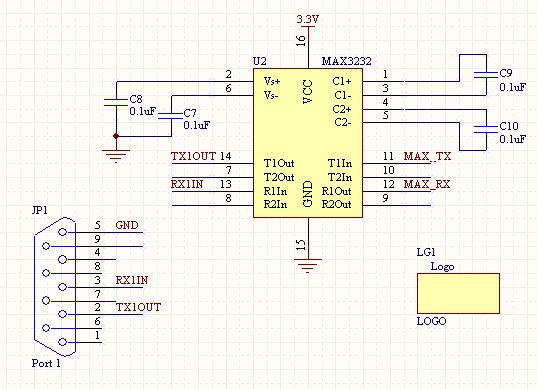
Once the setup of an RS232 connection is understood, it becomes a straightforward process for future projects. This design features a compact SMD version of the power supply, which can also be constructed using through-hole components on a breadboard....
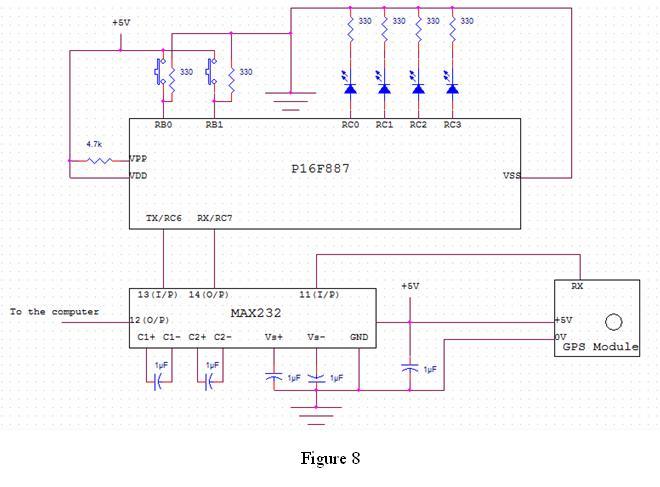
In this project, an embedded system is designed for tracking and positioning vehicles using the Global Positioning System (GPS) and Global System for Mobile Communications (GSM). The AT89S52 microcontroller interfaces with various hardware peripherals. The system continuously monitors a...
The anti-theft system includes two frequency sirens connected to the vehicle's immobilizer system. In the laboratory simulation model, the changes in operating modes, siren activation, and fuel supply cut-off are indicated by the illumination of LEDs and communicated to...
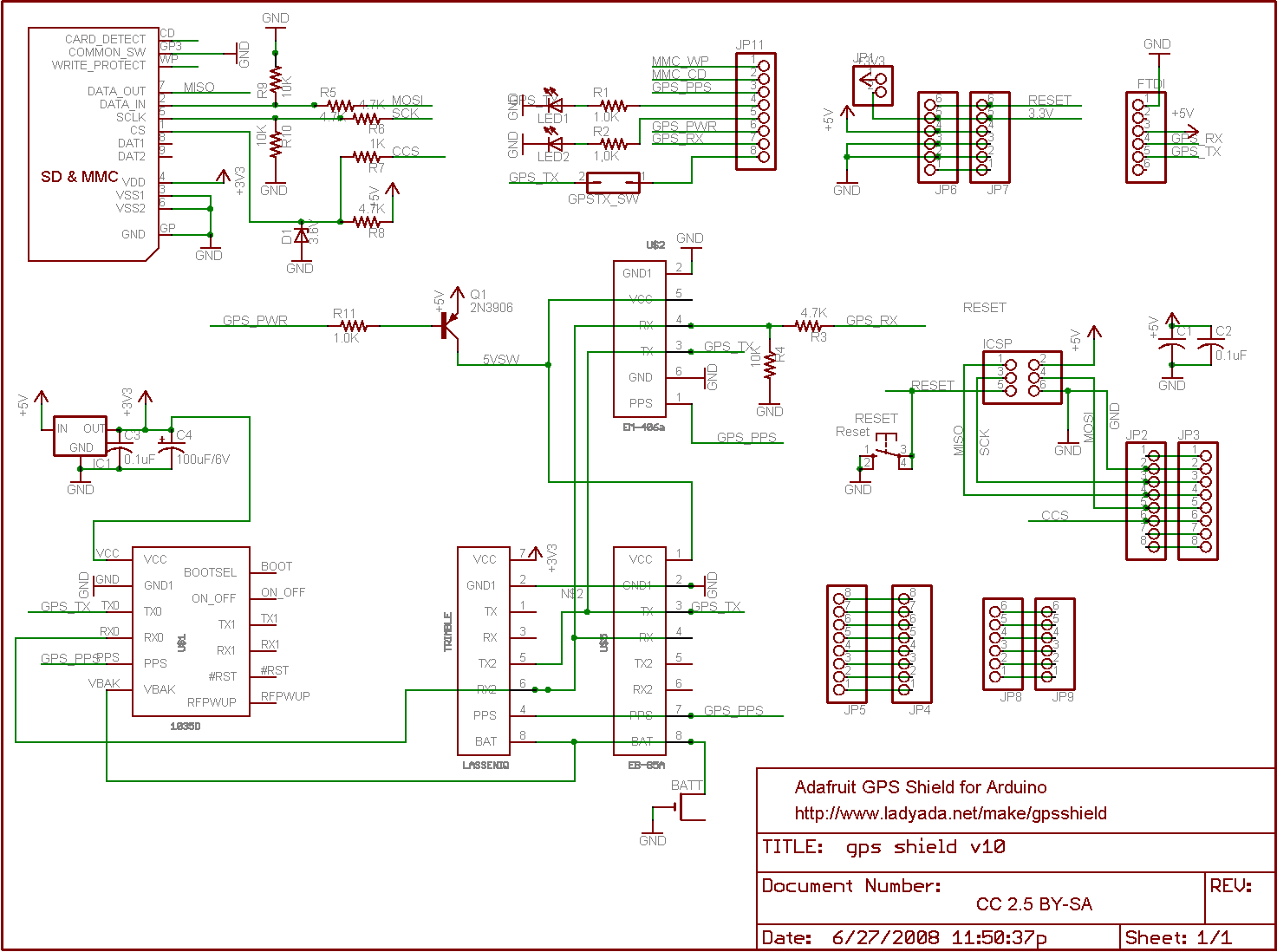
The SD library integrated into the Arduino IDE has replaced this code. Its only advantage is that it can fit and operate on an ATmega168 Arduino, making it potentially useful for users unable to upgrade. For all other cases,...
The yellow wires on the far right serve as temporary power connections, allowing battery power to enter through the contact studs located in the large holes that press against the radio's battery terminals. The cable in the lower right...
Hackers listen up. Everyone understands and enjoys the utilitarian benefits that GPS has brought to our lives but what if it didn’t work any more? I suppose you could build some sort of surface to space missile robot that...