
The schematic diagram fo Car Horn using IC 555

The car horn circuit schematic is designed to integrate various resistive and capacitive components to control the sound output of the horn. The circuit utilizes a combination of resistors (R1 to R7) and capacitors (C1 to C6) to shape the audio signal, ensuring that the horn produces a distinct sound that is suitable for automotive applications.
Resistors R1 (68K), R2 (2K2), R3 (56K), and R4 (3K3) serve to limit current flow and set the gain of the signal. R5 and R6, both rated at 4K7, are used for biasing purposes, while R7, a 10K potentiometer, allows for adjustable control over the circuit, enabling fine-tuning of the horn's volume or pitch.
The capacitors play a crucial role in filtering and coupling within the circuit. C1 and C2, each with a capacitance of 22nF, are likely used for high-frequency signal coupling, while C3 and C5, rated at 100nF, can serve as decoupling capacitors to stabilize the power supply and prevent noise. C4, with a value of 1nF, may be utilized for high-pass filtering, and C6 (22nF) further assists in signal processing.
This schematic is ideal for those looking to modify or enhance their vehicle's horn system, providing a clear and effective means to achieve desired sound characteristics through careful component selection and arrangement. Proper implementation of this circuit will ensure reliable operation and improved auditory signaling for automotive applications.The following diagram is the schematic diagram fo Car Horn, you may try this circuit for your car modification Components List: R1 = 68K R2 = 2K2 R3 = 56K R4 = 3K3 R5,R6 = 4K7 R7 = 10K Pot/trimpot C1,C2 = 22nF C3,C5 = 100nF C4 = 1nF C6 = 22.. 🔗 External reference
Related Circuits
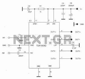
This stereo amplifier is designed for automotive applications and can deliver up to 2 x 22W using a single TDA1557Q or TDA1553Q from Philips. The stereo amplifier circuit utilizes the TDA1557Q or TDA1553Q integrated circuit, which is a high-performance...
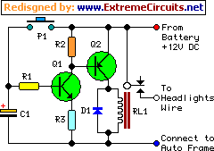
This device functions as a simple timer that keeps the vehicle's headlights on for approximately 1 minute and 30 seconds, allowing access to dark areas without the need to return and switch off the lights. Pressing switch P1 enables...
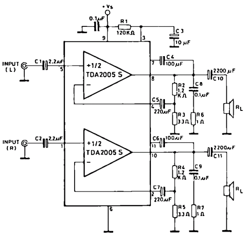
The TDA2005 integrated circuit (IC) features a high output power of 10W per channel (stereo) at a load of 2 ohms with a distortion of 10%, and 20W in bridge mode at a load of 4 ohms with a...
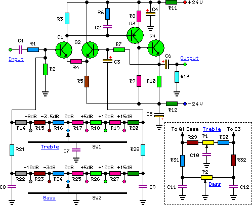
To complement the 60 Watt MOSFET audio amplifier, a high-quality preamplifier design was necessary. A discrete component topology, utilizing +24V and -24V supply rails, was selected, minimizing the transistor count while ensuring low noise, very low distortion, and a...
The SP1481E, SP1485E, SP1490E, and SP1491E series transceivers, combined with the SP6652 high-efficiency, high-frequency current mode PWM buck regulator, facilitate the creation of an isolated RS-485 interface capable of providing up to 2kVrms isolation. This configuration supports CAN communication...
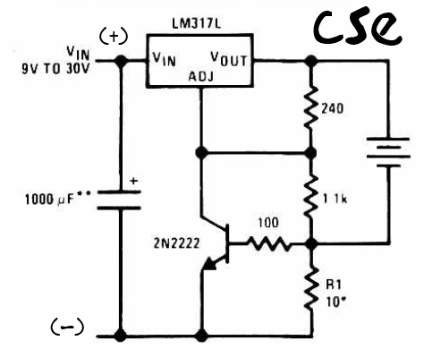
This is a straightforward charger designed for 9V to 30V batteries, primarily operated by the IC LM317L and a 2N222 transistor. It utilizes direct input DC voltage, and a recommended capacitor of 1000µF is included for filtering the output...