
The Sound Square

The next step involved designing the electronics, with the initial challenge being the spacing of the beams. If spaced too far apart, resolution diminishes; if too close, interference from adjacent beams occurs. This was addressed through three strategies: sourcing a narrow-angled infrared emitter, the OP298B, which has a half-angle beam width of 25 degrees and a high light output of 4.8mW at 100mA, and a matching detector, the BPV11F, which features a half-angle of 30 degrees. The BPV11F is a phototransistor with sufficient sensitivity to detect the beam without needing additional amplification and includes a built-in filter to reduce interference from visible light.
To further minimize stray light interference, 1" long tubes were fitted over the emitters and detectors, constructed from black art paper rolled around a pencil of the same diameter as the sensors. The ends were secured with double-sided sticky tape. Additionally, alternating the placement of sensors and emitters allows for closer spacing, effectively enabling the sensors to be placed twice as close together. The arrangement consists of emitters and sensors surrounding the space on all four sides, with columns labeled 'V' for vertical and rows labeled 'H' for horizontal. This configuration accommodates eight beams in each direction, resulting in 64 distinct sensing areas, sufficient for two independent sound banks.
Despite its effectiveness, the design is still vulnerable to light interference from adjacent beams or ambient light. This issue was mitigated by placing infrared filters over each phototransistor, ensuring that if only one phototransistor is triggered by stray light, the system remains inactive on that side. The initial spacing of the beams was set at 3.5 mm intervals, which could be increased to further reduce interference.
Regarding the interface design, the number of required computer input/output lines was significantly reduced. Although 16 emitters and 16 detectors would typically necessitate 32 I/O lines, this design condenses it to just four. By activating the emitters one at a time, only the detectors that correspond to the active emitter need to be monitored. In this implementation, two emitters are turned on simultaneously—one vertical and one horizontal—allowing detection to occur on either axis and further reducing the number of required computer inputs from 16 to just two. This optimization minimizes the complexity of the logic circuitry while maintaining functionality.On the face of it the design of a Sound Square is simple, all you need are several Infra red beams across an opening and when ever you place your hand in it you break one of the beams. Simply detect which beam is broken and you know where about the square your hand is, then convert that position into a note.
However, within that simple remit is alot of design and construction, not only because of the number of components in the system but also trying to minimise the hardware required. I decided to mount my components on a frame made of angle aluminium, it was an asymmetrical piece with the two sides being 1" by 2.
5". I didn`t use anything more fancy than a saw and a drill. The whole thing is held together by 4BA nuts and bolts although you can use metric ones if you want. Having constructed a mount for the components now came time to design the electronics. The first problem was knowing how far apart I could put the beams. Too far and there would not be much resolution, too close together and the light from one beam would spread out and interfere with the next detector. I tackled this on three fronts, first of all I scoured the component catalogues for a narrow angled Infra red emitter.
I found one in the OP298B, this has a half angle beam width of 25 degrees and a high light output, 4. 8mW at 100mA. A matching detector BPV11F was found with a half angle of 30 degrees. This is a photo transistor and has enough sensitivity to detect the beam without needing further amplification, further more it has a built in filter to minimise interference from visible light.
In order to reduce the stray light further I then fitted 1" long tubes over the emitters and detectors. I made these from black art paper rolled twice round a pencil the same diameter as the sensor. The ends of the roll were fixed with a little double sided sticky tape. The final way to reduce the effects on adjacent sensors is to alternate sensor and emitter, in this way the sensors can be twice as close, as if you had a row of emitters and a row of sensors.
This sounds quite complex but is quite simple, the basic idea is shown in Figure I below. Note that the space is surrounded on all four sides with emitters and sensors, each column is labelled V for vertical and each row H for horizontal. I managed to squeeze eight beams in each direction but this can be modified for your convenience. Still, having eight sensors enabled me to split the space into 64 different sensing areas, enough for two independent banks of sounds.
This design works well but it can still suffer from light interference either from adjacent beams or from stray day, or room light. I minimised this problem by putting infra red filters over each photo transistor. If only one photo transistor is triggered from stray light then nothing on that side will work. If you are making this hardware specifically for this project then you can space the beams further apart, this will also help to minimise spillage.
I originally had them at 3. 5 mm intervals but this could easily be doubled. Now when it comes to the interface you can usually trade extra hardware for computer input and outputs and this is no exception. On the face of it having 16 emitters and 16 detectors would require 32 computer I/O lines, my design reduces this to four!
I could have gone for three but that would have needed much more logic circuitry and not have been worth while. So how is this trick performed Well, if you switch the emitters on one at a time you only need to see if any of the detectors has seen a beam.
This is because if you know what light is on there is only one detector that can possibly have seen it. In fact in this design I decided to turn two emitters on at once, one vertical and the other horizontal.
Then I only need to know if I have a detection on the horizontal or vertical axis. So that cuts down the number of computer inputs from 16 to two. However, even 🔗 External reference
Related Circuits
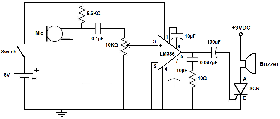
This circuit is designed to activate an alarm when it detects sound above a specified threshold. The alarm serves as a notification for any sound in areas that are typically quiet, such as quiet zones. Under normal quiet conditions,...
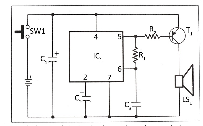
This document presents a verified circuit diagram for a simple, interesting, and cost-effective electronic clapper (sound generator) circuit, along with a description of its functionality. The electronic clapper circuit is designed to activate sound generation through the detection of sound...
This is a surround sound decoder. With this circuit, you can divide the 2-channel (right and left channel) stereo output into 4-channel output, which includes the right channel, left channel, center output, and rear output. This circuit will enhance...
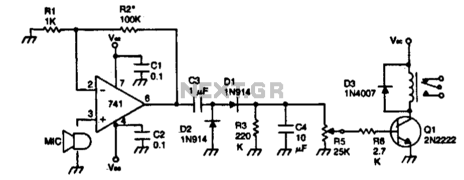
The device remains dormant (in an off condition) until a sound activates it. The input stage consists of a 741 operational amplifier configured as a non-inverting audio amplifier with a gain of approximately 100. To increase the gain, the...
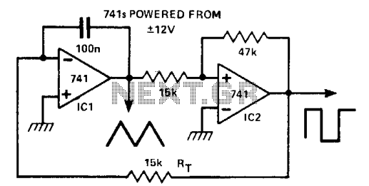
This circuit generates a triangle waveform and a square waveform simultaneously. It is self-starting and does not have latch-up issues. IC1 functions as an integrator with a slew rate determined by the capacitor (CT) and resistor (RT). IC2 acts...
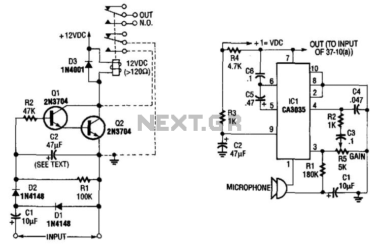
A sound-detecting alarm system can be constructed using a microphone, a high-gain amplifier, and a detector-relay driver. For a latching setup, connect the dotted lines to the relay as indicated in the schematic. The sound-detecting alarm system utilizes a microphone...