
Thermocouple amplifier

The input protection circuitry is designed to safeguard the amplifier from high voltage transients, specifically allowing a thermocouple to short to 120 Vac without incurring damage. This is crucial in applications where thermocouples are exposed to high voltage environments, ensuring the longevity and reliability of the amplifier.
For calibration, a 50 mV signal should be applied in place of the thermocouple. This serves as a reference input to adjust the output voltage accurately. The resistor R3 is then trimmed to achieve a specified output voltage (V0UT) of 12.25 V. This step is essential for ensuring that the amplifier responds correctly to the thermocouple's output during normal operation.
After the calibration of R3, the thermocouple should be reconnected to the circuit to resume normal function. Further fine-tuning is required by adjusting R9 to ensure the output is correct. This final adjustment allows for precise matching of the output signal to the expected values based on the thermocouple's characteristics, thereby ensuring accurate temperature measurements and system performance.
Overall, the combination of input protection and calibration steps ensures that the amplifier operates reliably in high-voltage environments while maintaining accurate readings from the thermocouple.Input protection circuitry allows thermocouple to short to 120 Vac without damaging the amplifier. Calibration: Apply a 50 mV signal in place of the thermocouple. Trim R3 for V0UT = 12.25 V. Reconnect the thermocouple. Trim R9 for correct output.
Related Circuits
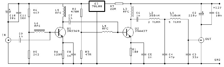
A high-efficiency, simple two-transistor VHF amplifier electronic circuit project can be developed using the provided circuit diagram. This VHF amplifier circuit achieves a significant efficiency with a gain of approximately 16 dB and does not require any tuning or...
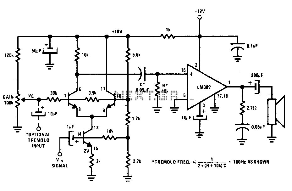
The transistors create a differential pair with an active current-source tail. This configuration, referred to as a variable-transconductance multiplier, produces an output that is proportional to the product of the two input signals. The multiplication effect arises from the...
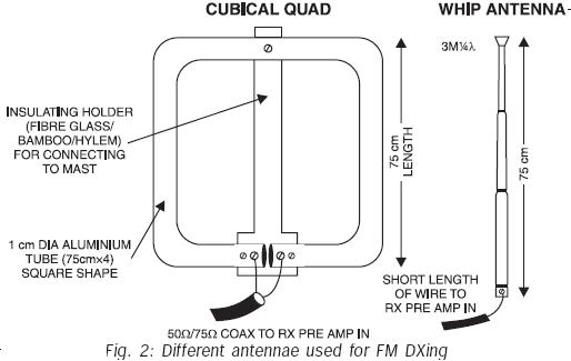
FM transmissions can be received within a range of 40 km. In fringe areas, the signal may be very weak. FM DXing refers to the practice of receiving distant stations (1500 km or more) on the FM band (88-108...
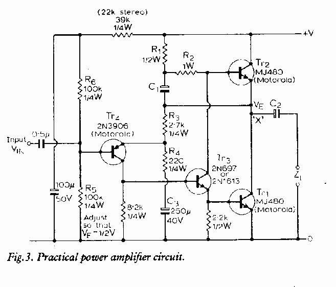
The major advantage of amplifiers of this type is that the normal static power dissipation is very low, and the overall power-conversion efficiency is high. Unfortunately, there are also some inherent disadvantages due to the intrinsic dissimilarity in the...
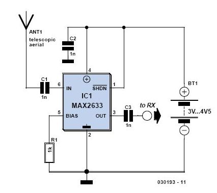
This is a high-performance radio receiver antenna amplifier designed for the entire VHF broadcast and PMR band (100-175 MHz) that can be successfully constructed without... This radio receiver antenna amplifier is engineered to enhance the signal quality and reception capabilities...
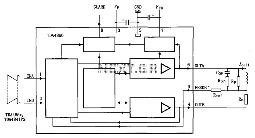
The TDA4866 is a 90-color power amplifier designed for vertical deflection systems, operating at a frequency range of 50 to 160 Hz. The CRMM circuit is implemented to ensure a high current drive input. The amplifier features a dual...