
THREE FREQUENCY AUDIO OSCILLATOR

The audio sine-wave generator circuit is designed to produce a stable sine wave output at various frequencies, making it suitable for audio testing and other applications requiring sine wave signals. The Wien bridge oscillator configuration is utilized, which is renowned for its ability to generate low-distortion sine waves.
In this circuit, resistors R1 and R2, along with capacitor pairs C2 to C7, establish the frequency of oscillation. The values of these components can be adjusted to achieve the desired output frequency. The configuration allows for the selection of different capacitor pairs, enabling three different frequency outputs, which can be easily switched depending on the application requirements.
The feedback mechanism is crucial for maintaining stable oscillations. Resistors R3 and R4, in conjunction with thermistor R7, form a negative-feedback loop that helps to regulate the amplitude of the output signal. The thermistor's resistance varies with temperature, which allows for automatic adjustment of gain, ensuring that the amplitude of the sine wave remains consistent even as conditions change.
Potentiometer VR1 offers the user control over the output level, allowing for fine adjustments to the amplitude of the sine wave signal. This feature is particularly useful in applications where precise signal levels are necessary.
Switch S2 serves as a means to introduce additional attenuation through resistor R6. This capability is beneficial for applications that require lower output levels without the need for additional external components. The choice of resistor value for R6 can significantly influence the degree of attenuation, with a 100 kΩ resistor providing a substantial reduction in output amplitude.
Overall, this audio sine-wave generator circuit is a versatile tool for generating high-quality sine wave signals, with features that allow for frequency selection, amplitude control, and stable operation across varying conditions.The full circuit diagram for the audio sine-wave generator is shown. Resistors R1 and R2 bias the noninverting (pin 3) input of IC1, and their parallel resistance forms one element of the Wien net-work. They are the equivalent of R1 in Fig. 1. The other resistor in the Wien network is R5. Three switched pairs of capacitors (C2 to C7) provide the u nit with its three different output frequencies. Resistors R3 and R4 bias the inverting (pin 2) input of IC1, and their parallel resistance also acts as one element of the negative-feedback network. Thermistor R7 is the other section of the negative-feedback circuit. An RA53 thermistor is the normal choice for this application, but because of its lower cost, an RA54 is used in this circuit.
Potentiometer VR1 is the variable-output attenuator. Opening switch S2 introduces losses through resistor R6 that reduce the output by about 20 dB. Use a value of 100 k © for R6 if a reduction by about 40 dB is preferred. 🔗 External reference
Related Circuits
The single-813 crystal oscillator transmitter, designed by RCA, was showcased in an advertisement on the back page of a 1938 "QST" magazine and published in the RCA HamTips bulletin, volume 1, number 4, dated December 1938. This transmitter delivers...
%2Bdecoder%2BCircuit%2Bschematic%2Busing%2BM8870.png)
This DTMF (Dual Tone Multi Frequency) decoder circuit identifies the dial tone from the telephone line and decodes the key pressed on the remote telephone. For the detection of DTMF signaling, the IC MT8870DE, a touch tone decoder IC,...
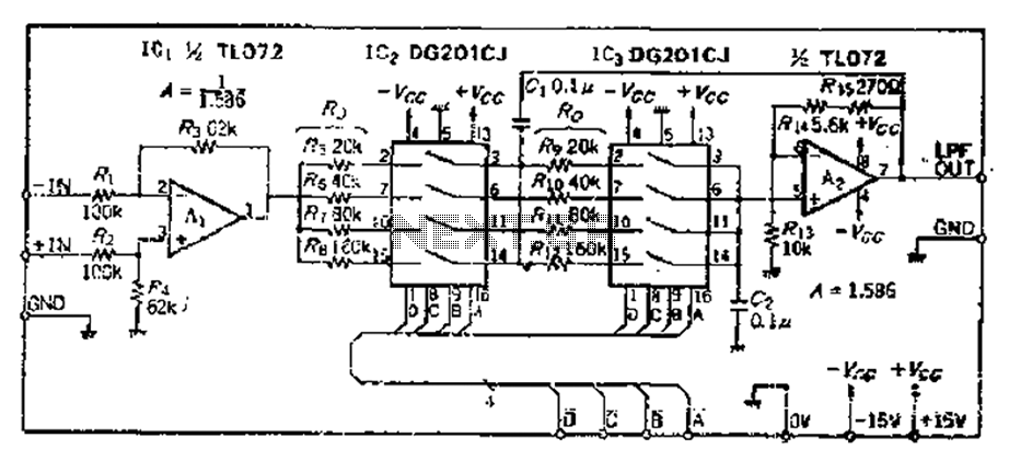
The circuit primarily consists of two Butterworth filters, designed to create a feedback amplifier with a gain of approximately 0.707. It features a differential input amplifier, where one input is grounded, resulting in a single input terminal. The attenuation...
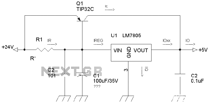
The circuit is a common three-terminal linear regulator expansion flow circuit. In practical applications, it may encounter some well-considered or lower false failures. 1. Disadvantages of this power supply: 1.1 This power supply is a linear regulator...
The input stage is comprised of both halves of a 6SL7 octal dual hi-mu triode in a differential amp configuration with a 1mA constant current cathode load. Field-effect (constant-current) diodes are used for simplicity. The differential amp approach was...
The amplifier's gain is nominally 20 dB. Its frequency response is determined primarily by the values of a few components, mainly C1 and R1. The schematic diagram values provide a response of ±3.0 dB from approximately 120 Hz to...