
Three of the five band equalizer circuit transistor

The circuit depicted in Figure 4-33 employs a common amplifier configuration, which is a foundational element in analog electronics. The common amplifier is characterized by its ability to provide significant voltage gain while maintaining stability within the circuit. The inclusion of analog inductive circuits allows for the manipulation of inductive components, which can be essential for various applications such as filtering or signal processing.
In this configuration, the transistor plays a crucial role in the analog inductive circuit. By increasing the bias resistor, the operating point of the transistor is adjusted, leading to improved thermal stability and performance. This adjustment is critical in ensuring that the amplifier operates within its optimal range, minimizing distortion and enhancing linearity.
The feedback loop of the amplifier is an integral part of its design, as it dictates the gain and stability of the overall system. The potentiometer connected to this feedback loop allows for fine-tuning of the circuit's response. By adjusting the potentiometer, the feedback can be modified, which influences the gain and bandwidth of the amplifier. The center tap of the potentiometer being grounded is a common practice, as it provides a reference point for the feedback voltage, ensuring consistent performance across varying conditions.
Overall, this circuit configuration exemplifies the interplay between biasing, feedback, and stability in amplifier design, making it suitable for a wide range of applications in electronic systems.Figure 4-33 and using substantially the same circuit configuration, the common amplifier and analog inductive circuits are provided, but its analog inductive circuit transistor increases a bias resistor, the circuit more stable. Adjusting potentiometer connected to the feedback loop of the amplifier, the center tap to ground.
Related Circuits
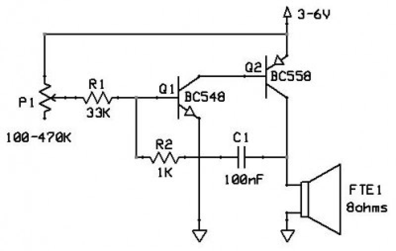
The application that we propose is a simple filter that limits the acoustic region (20-20000Hz) to the region 20-100Hz. With the manufacture proposed, an active filter can be created to drive a loudspeaker for very low frequencies. This allows...
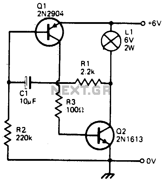
This simple circuit will flash a 6-volt lamp at a rate determined by the size of capacitor C1. It is most economical on power as it only draws current when the lamp is on. When the lamp is off,...
A compact power amplifier that delivers high-quality sound. It incorporates a NE5534 operational amplifier, known for its excellent performance, capable of handling low loads, providing high speed, and exhibiting low distortion. Additionally, it features two V-MOSFET transistors at the...
This circuit functions as an oscillator, capable of generating a sound wave or tone. The frequency of the tone, whether high or low, is adjustable via a variable resistor. The volume produced by this circuit is substantial; therefore, it...
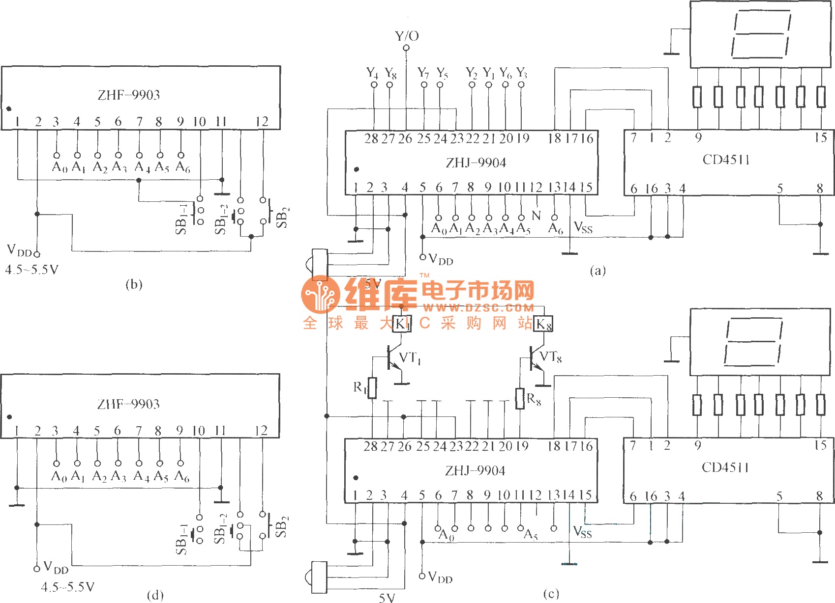
This is an eight-way signal remote control selection circuit composed of ZHJ-9904. It includes a remote control transmitter circuit, an eight-way switch control circuit, and a remote control transmitter. The eight-way signal remote control selection circuit utilizing the ZHJ-9904 is...
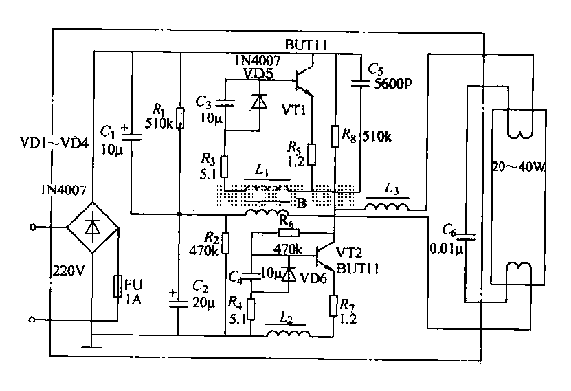
Electronic ballasts operate over a wide voltage range, provide fast startup with no noise or flicker, and contribute to energy savings. Their acceptance among users has been increasing. The circuit depicted in the figure represents a typical electronic ballast...