
Time-Delay Auto-Kill Switch Circuit

The automobile delayed kill switch is a safety mechanism designed to prevent unauthorized use of the vehicle by disabling the ignition system after a specified delay. This system can be implemented using a combination of electronic components, including a pushbutton switch, a timer circuit, and a relay.
The hidden pushbutton switch, which is activated when the driver exits the vehicle, is typically connected to a timer circuit. This circuit can be designed using a 555 timer IC in monostable mode, which provides a time delay before sending a signal to the relay. The time duration can be adjusted by changing the resistor and capacitor values in the timer circuit, allowing for customization based on user preference.
Once the timer expires, it triggers a relay that has normally open (NO) and normally closed (NC) contacts. The NO contacts are connected to the ignition system, specifically the wire leading to the ignition coil and the starter solenoid. When the relay is activated, it opens the circuit, effectively cutting off power to these components. This action ensures that if the engine is still running, it will cease operation immediately, and the starter will not engage, preventing any attempt to restart the engine while the kill switch is active.
To restore normal operation, a second pushbutton switch is installed inside the vehicle. Pressing this switch closes the relay circuit, returning the ignition system to its operational state. This two-switch mechanism enhances security, as both switches must be activated in their respective locations to enable the vehicle's ignition system.
In summary, the automobile delayed kill switch is an effective anti-theft device that employs a timer, pushbutton switches, and a relay to control the ignition system, ensuring that the vehicle cannot be easily restarted once the driver exits. The design can be further enhanced with additional features, such as LED indicators to show the status of the kill switch or a more sophisticated microcontroller for timing and control functions. The automobile delayed kill switch is simple in concept. When you get out of your car, a secretly located pushbutton switch is pressed. Nothing apparently happens, but at the end of a predetermined time, a relay is pulled in and locked. When the relay is pulled in, contacts open, and the hot lead from the ignition to the coil and the hot wire from the key switch to the starter solenoid is opened or disconnected. If the engine is running, it stops immediately and the starter will not operate. When you get into the car, another pushbutton switch is pressed and the relay drops out and everything goes back to normal.
Related Circuits
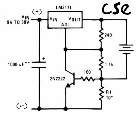
This is a straightforward charger designed for 9V to 30V batteries, primarily operated by the IC LM317L and a 2N222 transistor. It utilizes direct input DC voltage, and a recommended capacitor of 1000µF is included for filtering the output...
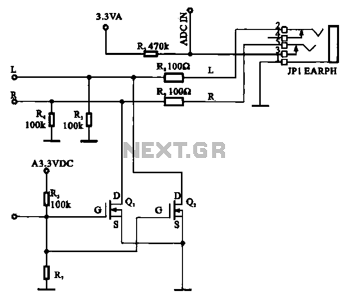
A field-effect transistor (FET) is utilized in a headphone circuit designed to function as a silencer tube. The circuit integrates L from the digital signal processing unit and R from the audio signal into the headphone jack's mute control...
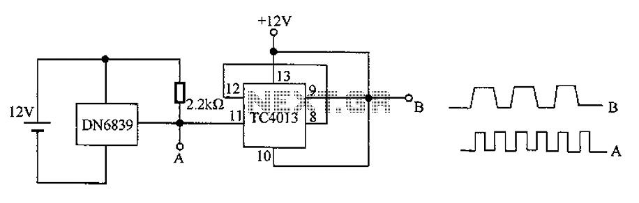
The circuit utilizes the integrated Hall element DN6839 for frequency division. It detects a magnetic field through the pulsating DN6839, generating a pulse waveform. The circuit is designed for applications involving very high-frequency pulsating magnetic fields. It employs the...
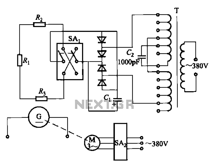
The AR-300 DC arc welding machine circuit includes the AX, AX1, AX3, and AR series. The structure of these machines is fundamentally similar, consisting of a three-integral unit converter, a phase asynchronous motor, and a DC arc welding generator...

The ESR Meter is essentially an AC Ohmmeter equipped with specialized scales and protective circuitry. It provides continuous readings of series resistance in electrolytic capacitors. Operating at 100 kHz, it maintains the capacitive reactance factor close to zero. The...
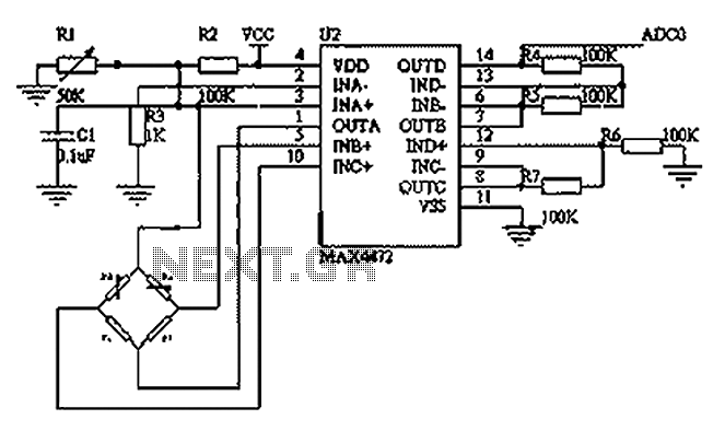
This circuit utilizes a BP01-type pressure sensor and the MAX4472 operational amplifier. The BP01 pressure sensor is specifically designed for blood pressure detection and is primarily used in portable electronic sphygmomanometers. It features a precision thick film ceramic chip...