
TL494 regulator for the current application

A double-loop speed control system for brushless DC motors is designed to enhance the precision of motor speed regulation. The system employs a speed controller that outputs a torque or current signal to effectively manage the motor's performance. The TL494 integrated circuit serves a dual purpose, functioning both as a current regulator and a current limiter. This dual functionality is critical for maintaining optimal performance and protecting the motor from overcurrent conditions.
In this system, current feedback is monitored through input pin 1, which provides real-time data on the motor's operational status. The command current, which is the desired current level for the motor, is fed into the system via pin 2. An error amplifier is employed to compare the actual current feedback against the command current, generating an error signal that is utilized by the PI (Proportional-Integral) regulator. This regulator adjusts the PWM (Pulse Width Modulation) signal output to minimize the error, thus ensuring that the motor operates at the intended speed.
The PWM signal generated by the PI regulator is crucial for controlling the voltage and current supplied to the motor. To improve the system's response time and stability, the comparison method used for the PWM signal is serrated ferry crossing. This method is preferred over traditional triangle wave or sawtooth edge comparisons because of its steeper characteristics, which significantly reduce the likelihood of current fluctuations during the rapid on-off switching cycles inherent in PWM control. By minimizing these fluctuations, the system enhances the motor's performance, ensuring smoother operation and improved efficiency.
Overall, this comprehensive control system design allows for precise management of brushless DC motors, leveraging advanced feedback mechanisms and innovative comparison techniques to achieve superior control and reliability.DC motor (brushless DC motor) double-loop speed control system, the speed controller output torque (or current) signal given. It can be used TL494 as a current regulator and cu rrent limiter (see Figure 10-3). Current feedback detection signal from the input pin l, the command current J from 2 feet input, the error amplifier is connected to a PI regulator mode, PWM signal. As a comparison here with serrated ferry crossing, the effect is better than the triangle wave, sawtooth edge because the very steep, avoid the fluctuations in current caused by the switching time multiple on-off current PWM signal generating images.
Related Circuits

To create a telephone ring monitor, it is sufficient to connect a resistor in series with a bulb and plug it into a main outlet. The resistance value of this resistor may vary depending on the type of bulb...
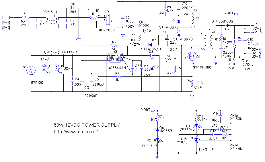
This is a simple, low-cost 50W off-line switching power supply designed for home projects or for learning about the operation of flyback converters. It operates over a universal AC input range of 90-264 VAC and provides a 12V DC...
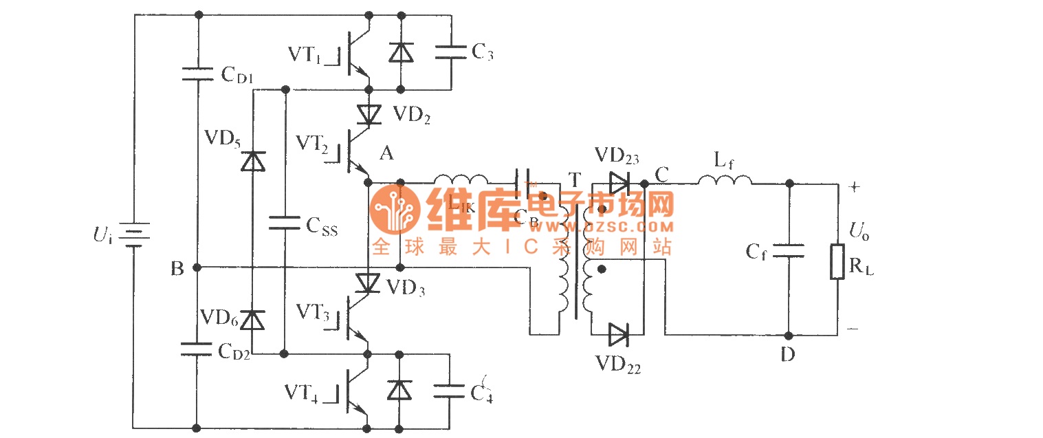
To eliminate circulating current in a zero-voltage switch three-level DC converter during its zero state, a zero-voltage zero-current switch three-level DC converter circuit has been proposed. The primary distinction between this circuit and the standard zero-voltage switch three-level DC...
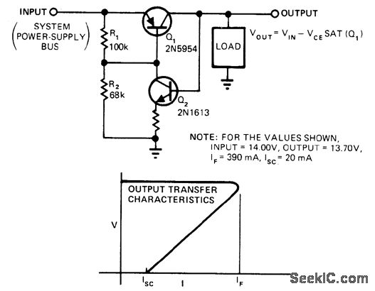
This circuit provides overload and short-circuit protection for a load while isolating malfunctioning circuits from other loads on a common supply bus. During normal operation, transistor Q1 is in saturation. When the load attempts to draw more current than...
The circuit's current exceeds the load carried by the rated current meter, prompting the user to immediately cut off the power supply to address the overload. Pressing the reset button restores power, making the system simple, convenient, and practical....
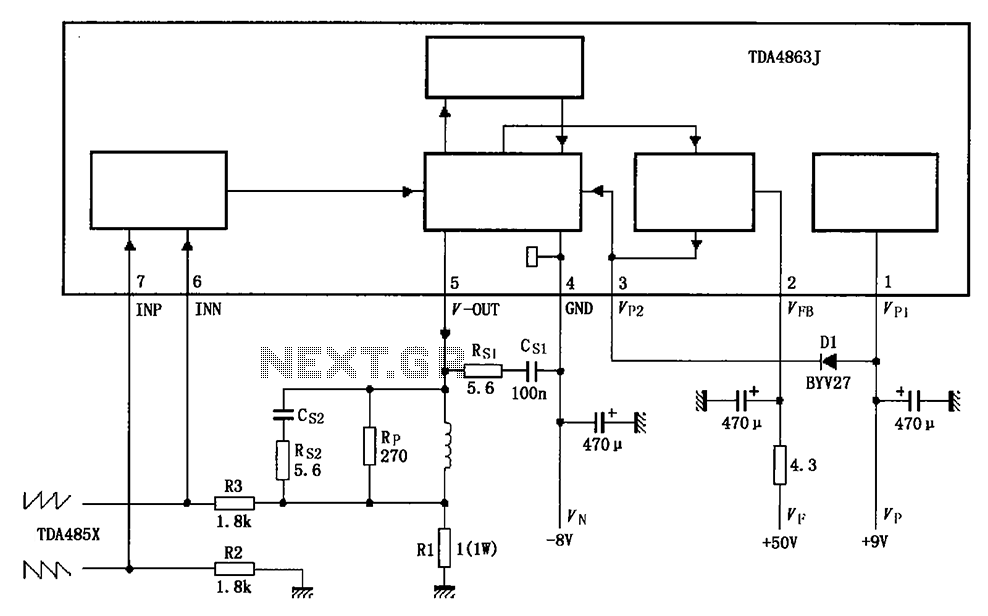
The TDA4863J basic application circuit operates with a positive supply voltage (VP), a flyback power supply voltage (VF), and a negative supply voltage (VN). The input signal is provided from the sawtooth signal input at pins 6 and 7,...