
Touch Activated Alarm System

The 555 timer circuit operates in monostable mode, where it generates a single output pulse in response to a trigger input. The circuit consists of the 555 timer IC, a resistor (R1), a potentiometer (P1), and a capacitor (C1). The pulse width (T) is determined by the values of R1, P1, and C1, with the formula T = 1.1 * (R1 + P1) * C1 guiding the selection of component values.
For the capacitor C1, it is essential to select a capacitor with a voltage rating that exceeds the supply voltage. This ensures reliability and longevity under normal operating conditions. The choice of a 12V power source necessitates a capacitor with a minimum rating of 25V to provide a safety margin.
The relay, which serves as the output device, can be any suitable type, such as an electromechanical relay or a solid-state relay, depending on the application requirements. The relay is activated when the circuit is triggered by a touch on the trigger wire connected to pin 2 of the 555 timer. This design allows for a simple user interface while maintaining security.
In terms of layout, it is crucial to ensure that all connections are secure and that the circuit is housed in a non-conductive enclosure to prevent accidental grounding. The inclusion of a RESET switch allows for manual resetting of the circuit, enhancing control over the operation.
The circuit's design also includes a delay feature to mitigate false triggering, which is particularly useful in environments where inadvertent touches may occur. The use of a ceramic capacitor at pin 5, while optional, can improve stability in electrically noisy environments.
Overall, this 555 timer-based circuit provides an effective solution for applications requiring controlled timing and relay activation, with considerations for safety, reliability, and user interaction.The 555 can be almost any type, they are all pin-compatible. Although some CMOS types may not have enough power to drive the transistor, in that case use an ordinary 555. C1`s working voltage should be increased to 25V if you decide to go with a 12V power source. Change the value of C1 for the desired output pulse. For the timing use this equation: T=1. 1*(R1+P1)*C1 assuming R1 + P1 = 150K, then select C1 as follows: C1 = 6 µF for each 1-second pulse width. For example, if you want the pulse width to be 5 seconds, C1 should be 30uf or nearest value like 22 or 33 µF.
Additionally, P1 can adjust the rest. Rule of thumb: the working voltage of capacitors are at least double the supplied voltage, in other words, if the power source is 9Volt, your capacitor(s) is at least 18V. Transistor T1 can be any approximate substitute. Use any suitable relay for your project and if you`re not tight on space, use any size. I`ve build this particular circuit to prevent students from fiddling with the security cameras in computer labs at the University I am employed.
I made sure the metal casing was not grounded. But as the schematic shows you can basically hook it up to any type of metal surface. I used a 12-vdc power source. Use any suitable relay to handle your requirements. A `RESET` switch (Normally Closed) can be added between the positive and the `arrow-with-the-+`. The trigger (touch) wire is connected to pin 2 of the 555 and will trigger the relay, using your body resistance, when touched. It is obvious that the `touching` part has to be clean and makes good contact with the trigger wire. This particular circuit may not be suitable for all applications. Just in case you wonder why pin 5 is not listed in the schematic diagram; it is not really needed. In certain noisy conditions a small 0. 01µF; ceramic capacitor is placed between pin 5 and ground. It does no harm to add one or leave it out. NOTE: For those of you who did not notice, there is an approximate 5-second delay build-in before activation of the relay to avoid false triggering, or a `would-be` thief, etc.
AGAIN, make sure the latch (pin 2) is not touching anything `ground` or the circuit just keeps resetting itself and so will not work. My shed has wooden doors so works fine. If you can`t get yours to work, check the trigger input, verify there is some sort of signal coming from output pin 3, play with the value of R3/C1, etc.
🔗 External reference
Related Circuits
A circuit that offers visual indication of fluid level in a vessel, with a switchable audible alarm. Example uses would be to monitor the level of water in a bath or cold storage tank. Conductance is the reciprocal of...

This 555 timer circuit temperature monitoring system project can monitor temperature at up to four points. The system allows for the selection of whether the alarm should be triggered when the temperature increases or decreases, depending on the resistance...
This circuit consists of a 6 Zone Alarm system with an LED display. The alarm system features 6 independent zones and includes a 7-segment LED display, along with one timed entry/exit zone. The 6 Zone Alarm system is designed to...
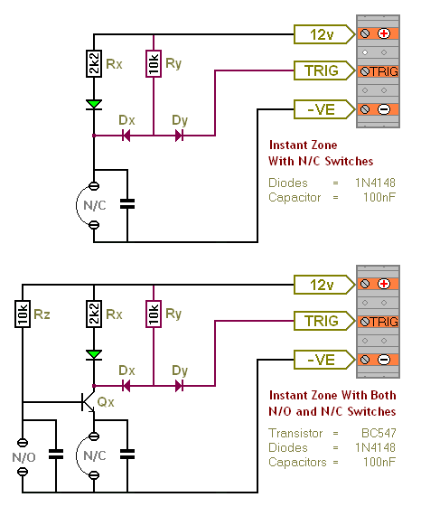
The Transistor Burglar Alarm System allows for the addition of multiple extra zones. The primary circuit is compatible with standard normally-closed input devices, including magnetic reed contacts, micro switches, foil tape, and passive infrared sensors (PIRs). An auxiliary circuit...
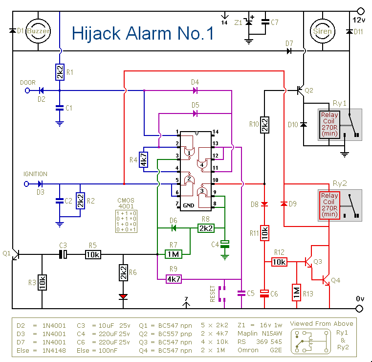
Before installing this or any other engine cut-off device in a vehicle, it is essential to carefully evaluate the safety implications of potential failures and the legal ramifications of implementing a device that could result in an accident. If...

The SA608 is a low-voltage, high-performance monolithic FM intermediate frequency (IF) system that includes a mixer, oscillator, two limiting intermediate frequency amplifiers, a quadrature detector, a logarithmic received signal strength indicator (RSSI), a voltage regulator, and audio and RSSI...