
Touch Switch with MPF102 JFET

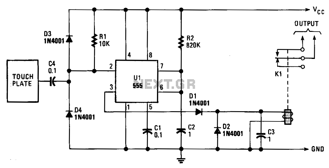
The circuit operates as a touch-sensitive switch, utilizing the principles of capacitive sensing. When a substantial conductive object approaches the touch plate, it introduces a change in capacitance that induces a voltage signal due to the stray 60 Hz electromagnetic interference commonly present in the environment. Diodes D1 and D2 serve to rectify this alternating current (AC) signal, converting it into a direct current (DC) signal.
The rectified voltage is applied across the resistor R2 and capacitor C2, creating a negative voltage potential at the gate of transistor Q1. This negative voltage effectively switches off Q1, which is normally in a conducting state, allowing the current path to change. As Q1 turns off, it triggers Q2 to conduct, resulting in a low output state from the circuit.
The configuration ensures that Q2 remains in a cut-off state under normal conditions, as Q1 is usually conducting. This design provides stability and prevents false triggering from minor disturbances. The choice of components, such as the values of R2 and C2, is crucial as they determine the sensitivity and response time of the touch-sensitive switch. The circuit can be utilized in various applications, including touch-sensitive controls in consumer electronics, security systems, and automation devices. Proper layout and shielding may be necessary to minimize interference and ensure reliable operation in different environments.When the touch plate is contacted by a large object (human body, etc.), stray 60-?? pickup is rectified by D1 and D2, and produces a negative voltage across R2-C2 and the gate of Q 1. Q1 cuts off, causes Q2 to conduct, and the output goes low. Q2 is held cut off since Q1 normally is conducting.
Related Circuits
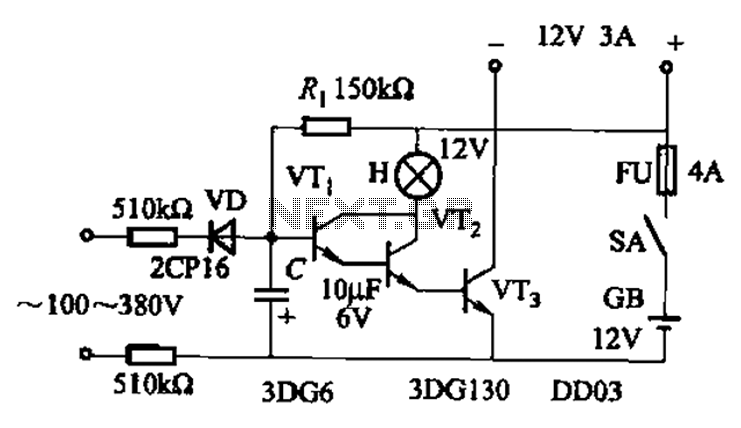
An AC-DC power supply without a power switching circuit is typically utilized for lighting load circuits. Once the power grid is restored, the standby power supply automatically switches on. An automatic switching circuit using a transistor is implemented, with...
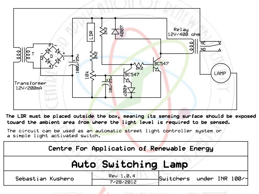
The light-activated switch circuit can be used for switching off a particular lamp or group of lamps in response to varying ambient light levels. The light-activated switch circuit utilizes a light-dependent resistor (LDR) as the primary sensing element to detect...
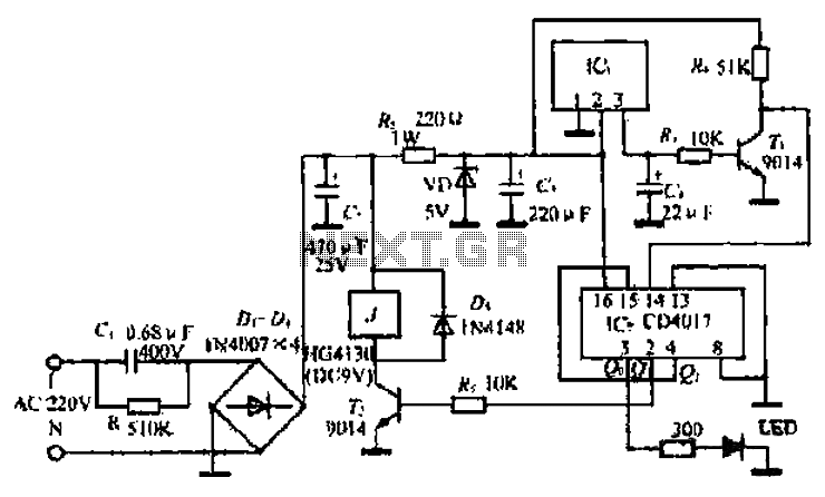
Normally, home appliances are controlled using switches, sensors, etc. However, physical contact with switches may be dangerous if there is any shorting. The circuit described here requires no physical contact for operating the appliance. It only requires moving a...
The ML4423 is an integrated controller designed for single-phase and two-phase AC induction motors. It features PWM (Pulse Width Modulation) capabilities for speed control and includes various protection circuits such as short circuit protection, fire protection, and a reference...
This is same circuit as above with the addition of a photo resistor to trigger the flip flop instead of a push button. The bias resistor in series with photo resistor was chosen so that sufficient voltage is present...
The monostable period is set for approximately 1 second, which is typical for this application. The induced line hum is transmitted through capacitor C2, resulting in a continuous stream of trigger pulses. The output remains low for about 10...