
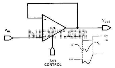
Track-and-hold-sample-and-hold

Channel 1 is configured as a voltage follower and is activated during the track/sample time. If the product of R and C is sufficiently short compared to the period of maximum output frequency or sample time, then C will charge to the output level. Channel 2 functions as an integrator with no input signal. When Channel 2 is activated, the output will maintain the voltage across C.
Channel 1 operates as a voltage follower, a configuration commonly used in electronic circuits to buffer signals. This setup ensures that the output voltage closely follows the input voltage while providing high input impedance and low output impedance. The activation of Channel 1 during the track/sample time allows for accurate tracking of the input signal. The relationship between the resistor (R) and the capacitor (C) is critical; specifically, the time constant τ (tau), defined as τ = R × C, must be minimized in relation to the frequency of the input signal. When this condition is satisfied, the capacitor will charge effectively to the output voltage level, ensuring that the output remains stable and accurate during the sampling period.
Channel 2 is designed as an integrator, which is a fundamental operation in signal processing. In this configuration, the output voltage is proportional to the integral of the input signal over time. When there is no input signal, the integrator will maintain its output voltage at the level determined by the charge across the capacitor (C). This characteristic is crucial for applications where a stable reference voltage is required when no active signal is present. When Channel 2 is activated, it will hold this voltage, effectively allowing the circuit to retain information even in the absence of an input signal. The integration process can be influenced by the values of the components used in the circuit, particularly the feedback resistor and the capacitor, which together define the response time and stability of the integrator.
Overall, the interaction between these two channels provides a robust method for processing signals in a variety of electronic applications, ensuring that both tracking and integration functions are performed with high fidelity.Channel 1 is wired as a voltage follower and is turned on during the track/sample time. Ifthe product of R x Cis sufficiently short compared to the period of maximum output frequency, or sample time; Cwill charge to the output level. Channel2 is an integrator with zero input signal. When channel2 is then turned on, the output will remain at the voltage across C.
Related Circuits
Feedback operates similarly to a conventional operational amplifier (op-amp) voltage follower, providing 11 unity-gain, non-inverting outputs. This configuration also features a very high input impedance. The primary distinction between a track-and-hold and a sample-and-hold lies in the duration for...