
Tube Power Amplifier with EL34 - 35W circuit

The described amplifier features a push-pull topology, which is well-known for its efficiency in audio amplification. The use of two EL34 vacuum tubes allows for a robust output of 35 watts, making it suitable for driving speakers in various audio applications. The push-pull configuration provides advantages such as reduced distortion and improved linearity, which are crucial for high-fidelity sound reproduction.
The circuit likely includes a power supply section designed to provide the necessary high voltage for the EL34 tubes, as well as filament voltage for their operation. The output stage would typically incorporate an output transformer, which matches the high-impedance output of the tubes to the low-impedance load of the speakers. Additionally, feedback mechanisms may be implemented to further enhance performance by stabilizing gain and reducing distortion.
Given the long operational lifespan of the amplifier, it is essential to consider the durability and reliability of components used in the design. High-quality capacitors and resistors would be necessary to maintain performance over time, especially under continuous use for 15 hours daily. The original design from 1953 reflects the engineering standards of the era while providing a foundation for audio amplification that remains appreciated by enthusiasts today.It`s a classic designing of final amplifier 35 W, with two EL34 in push-pull, from the Siemens and Halske, with year of designing 24/3/1953 and code SV410/1. The amplifier it worked from 1954 until 1989, whenever it came also out except operation, with mean of operation 15 hours per day..
🔗 External reference
Related Circuits
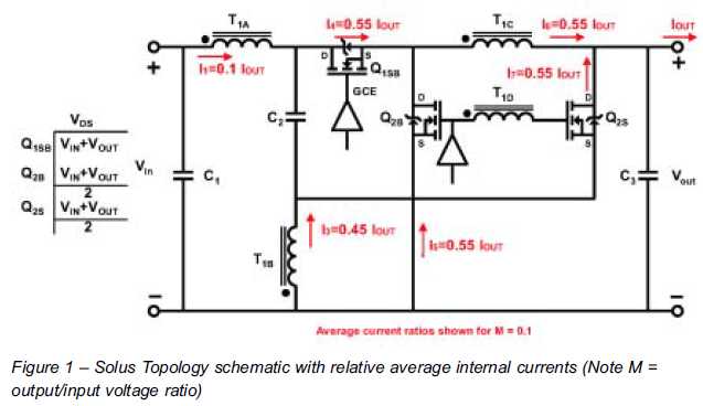
The ability to reduce power losses is crucial. This document describes a new ultra-high-performance topology that is expected to serve as the foundation for next-generation DC-DC power supplies in high-demand applications. The proposed ultra-high-performance topology aims to significantly enhance the...
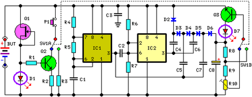
This circuit performs a rapid battery test without requiring a power supply or costly moving-coil voltmeters. It offers two testing ranges: when switch SW1 is positioned as indicated in the circuit diagram, the device can test batteries ranging from...
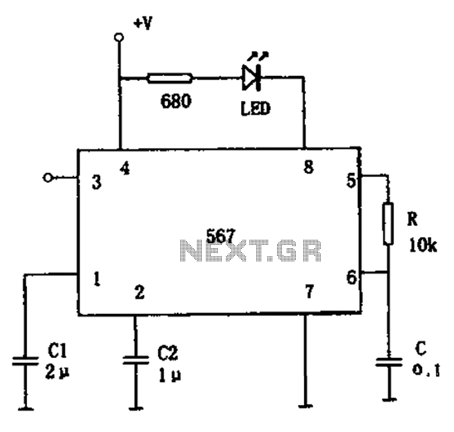
The FM demodulation circuit is illustrated in Figure 567. The FM signal is input at pin 3, and the demodulated signal is output from pin 5. The center frequency of the FM demodulation circuit is determined by the formula...
This document contains a collection of schematic diagrams, datasheets, images, and tips for switch mode power supplies (SMPS) utilizing the TL494, LM339, KA7500, and IC2003 integrated circuits. Switch Mode Power Supplies (SMPS) are crucial components in modern electronic devices, providing...

A simple frequency meter or frequency counter circuit featuring an LCD display and an AVR microcontroller. This includes a DIY schematic circuit diagram and embedded C code. The frequency meter circuit is designed to measure the frequency of input signals...
The roles of capacitors C1, C4, and C5 in a circuit may not be immediately clear. Capacitors on the power rail help to smooth out the signal by reducing current ripple, which can be observed using an oscilloscope. Resistors...