
Two electric motors on the mechanical brake circuit

The circuit operates by integrating a three-phase rectifier configuration that converts the AC supply voltage into a pulsating DC voltage, which is then applied to the motor stator windings. This method allows for effective control of the motor's deceleration and stopping process. The use of half-wave rectification means that only one half of the AC waveform is utilized, which can lead to a reduction in the overall power delivered to the motor during braking.
The inclusion of a short-circuit circuit is crucial for enhancing the braking effect. When the motor is commanded to stop, the contact KMi opens, disconnecting the motor from the power source and allowing the current to flow through the short-circuit path. This creates a strong magnetic field that opposes the rotor's motion, facilitating rapid braking. The electromagnetic braking action works in conjunction with the half-wave rectified current to provide a smoother and more controlled stopping process.
The adjustable time relay, KT, plays a vital role in determining the duration of the braking effect. By fine-tuning the relay settings, the user can achieve the desired stopping time, which is essential for applications where precise movement control is required. This feature is particularly beneficial in scenarios where the motor is subject to varying load conditions or where the stopping distance must be minimized.
In summary, the circuit in Figure 3-157 effectively combines half-wave rectification and electromagnetic braking to deliver precise motor control for applications requiring accurate stopping. The adjustable time relay further enhances the circuit's versatility, making it suitable for a variety of industrial and automation tasks.Circuit shown in Figure 3-157. The circuit can be used motor capacity of not more than llkW and require precise stopping of the occasion. Shutdown, contact KMi release, Mi and M2 motor stator winding is formed of three rectifier circuit and three short road circuit.
So the half-wave rectified current through the motor stator windings braking action, but also to exclude the rotor swing, plus short-circuit current of the electromagnetic braking action, we can achieve better braking effect. The length of time the brake is achieved by an adjustable time relay KT.
Related Circuits

This 555 timer circuit temperature monitoring system project can monitor temperature at up to four points. The system allows for the selection of whether the alarm should be triggered when the temperature increases or decreases, depending on the resistance...
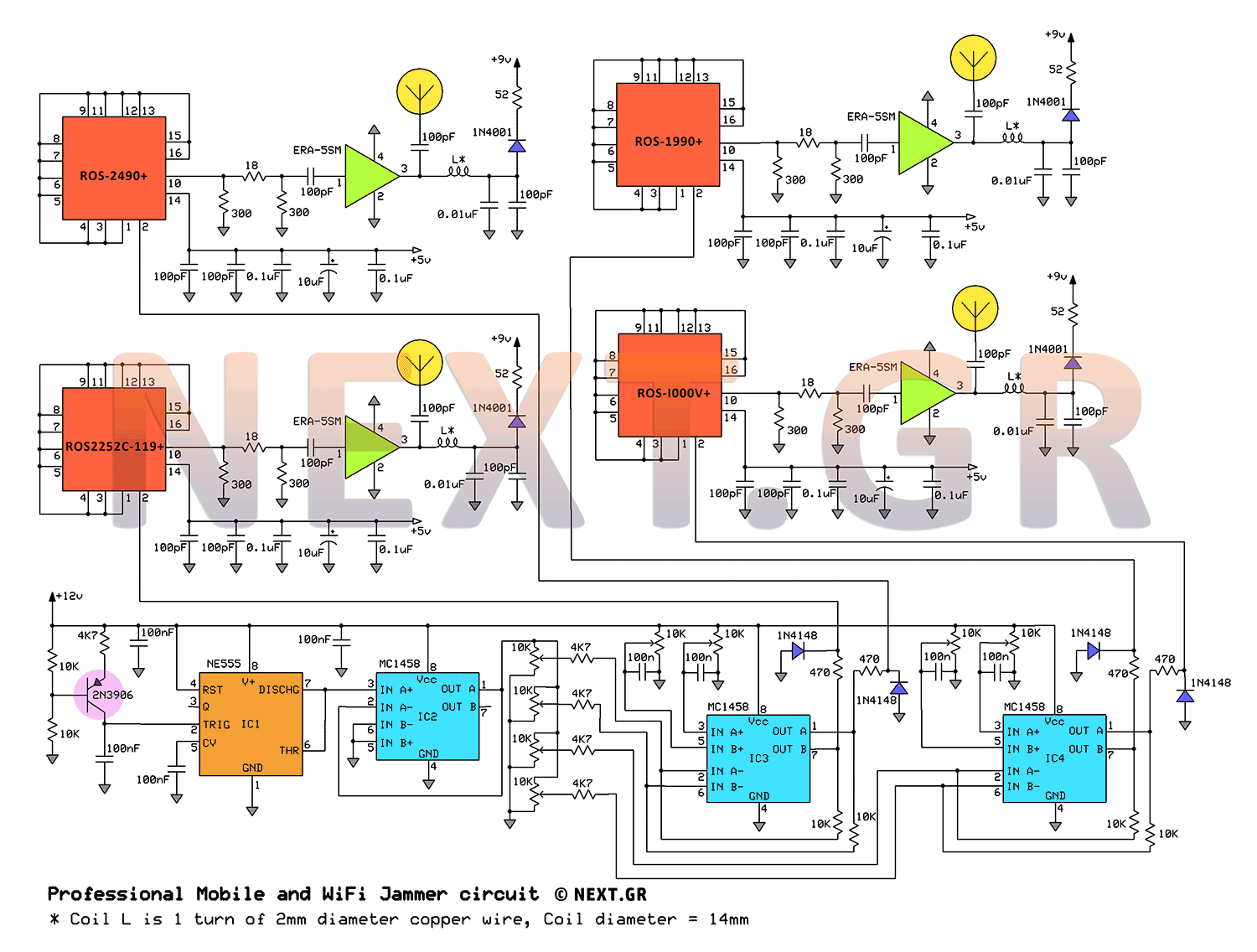
This jammer circuit can be utilized both indoors and outdoors, providing a coverage range of approximately 30 meters to disconnect wireless devices from their communication with the base station. The circuit design employs frequency ranges allocated to mobile operators,...
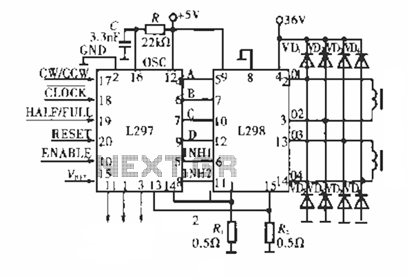
The circuit operates using a dedicated stepping motor controller, the L297. Pin 17 (CW/CCW) is utilized to control the rotation direction of the stepper motor. Pin 18 (CLOCK) regulates the speed of the stepper motor, while pin 19 (HALF/FULL)...
The danger always exists when fuel gases such as propane or natural gas are confined to a small area. The toxic gas alarm utilizes a tin-oxide semiconductor. A coil of thin wire is heated by a 12 V battery...
This is a beta release schematic. Use at your own risk. The idea is to add this circuitry to a board that already has RAM at address 2000 and an 82C55 I/O chip to provide ports A, B, and...
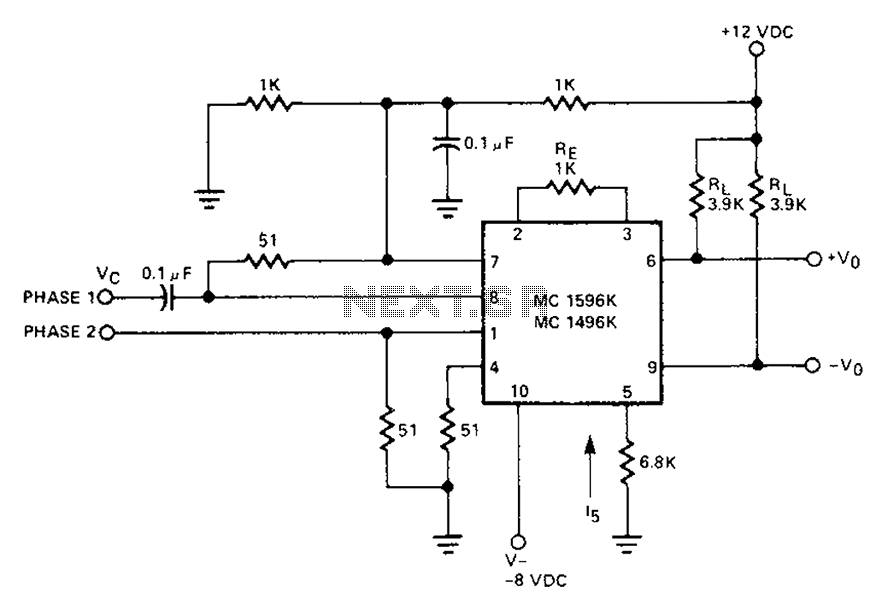
The circuit involves a Signetic balance modem connection utilizing a transistor array as a phase detector. It provides information about the cosine of the phase angle, which corresponds to the frequency of the input signal combined with the integrated...