
Two star flasher circuit

The circuit operates using the NE555 timer in astable mode, generating a continuous square wave output. The frequency of this output is determined by the resistors R1 and R2, as well as the capacitor C1, which together set the timing intervals for the flashing sequence. The output pulse from the NE555 triggers Q1, which is typically a bipolar junction transistor (BJT) or a MOSFET, allowing current to flow to the relay coil.
Relay K1 serves as a switch to control the lamps L1 and L2. When activated, it connects the power supply to lamp L2 through its N/O contact. As the NE555 output transitions low, Q1 turns off, the relay coil is de-energized, and the connection to lamp L2 is interrupted. The relay's N/C contact then completes the circuit for lamp L1, causing it to illuminate.
The overall design allows for a visually appealing effect suitable for decorative lighting during festive occasions. The adjustable timing through R2 provides flexibility in the flashing speed, enabling customization according to user preference. Proper selection of components, including the relay's current rating and the lamps' voltage and power specifications, is crucial to ensure reliable operation and safety. Additionally, consideration should be given to the power supply voltage to match the requirements of the NE555 and the relay.A circuit that can be used to flash two Christmas stars alternatively is given here. The IC1 NE 555 is wired as an astable multivibrator here. When there is a positive pulse from the output of IC1, the transistor Q1 conducts and the relay K1 gets activated. The lamp L2 connected via the N/O contact of the relay glows. When the output pulse of the IC goes low, the Q1 goes OFF and the relay gets deactivated. Now the lamp L2 extinguishes and the lamp L1 connected via the N/C contact of the relay glows. This cycle continues as long as there is power supply for the circuit. The timing of the lamps can be adjusted by varying the preset R2. 🔗 External reference
Related Circuits
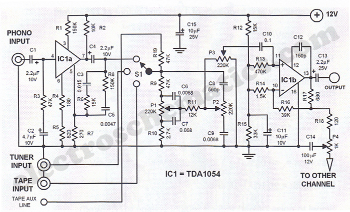
This Hi-Fi stereo preamplifier circuit is designed using the TDA1054 integrated circuit from SGS. The TDA1054 is a 16-pin DIL package that incorporates two separate preamplifier circuits. It is a low-noise preamplifier with minimal complications in the design process....
This circuit utilizes a single 555 Timer IC along with a small transformer to generate high voltage for testing zener diodes with voltage ratings up to 50VDC. The 555 timer operates in astable mode, with the output from pin...
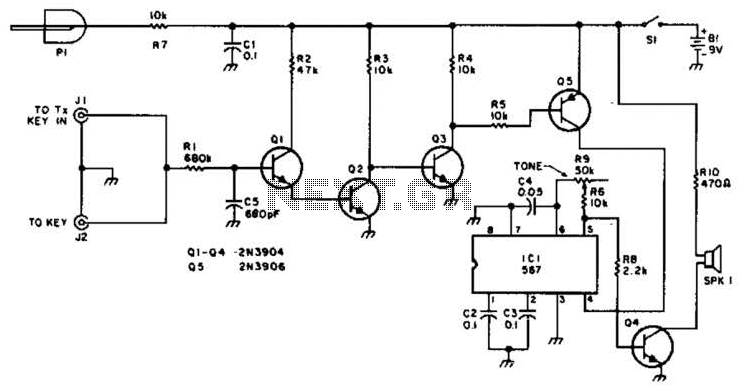
For use with low-power transmitters that require a positive keying voltage. The transistors Q1, Q2, and Q3 are configured as a switching amplifier. When the key is pressed, the collector of Q3 is pulled to ground, which activates Q5...
The TX05C-R infrared surveillance alarm circuit is designed for monitoring walls, windows, doors, and various restricted areas. When an intrusion occurs, the alarm activates to enhance security. The circuit comprises a transmitter module, a receiver module, a time-base circuit,...
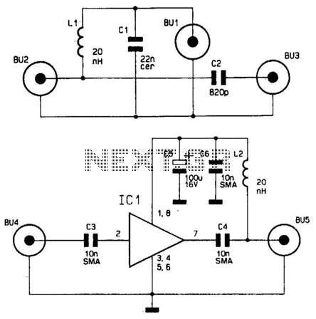
This wideband antenna preamplifier has a gain of approximately 20 dB from 40 to 860 MHz, covering the entire VHF, FM, commercial, and UHF bands. A phantom power supply delivers DC power to the preamplifier through the coaxial cable...
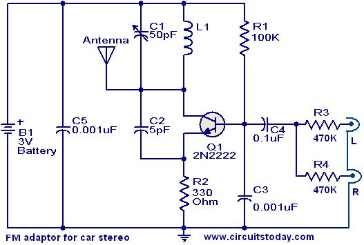
This compact FM adapter circuit, when connected to the audio output of a cassette player or iPod, enables the user to listen to their favorite music through a car stereo. It is particularly useful for vehicles that lack an...