
uhf tv pre amplifier

The UHF-TV preamplifier circuit is designed to amplify weak UHF signals, enhancing the reception quality for television broadcasts. The choice of the MPSH10 transistor, along with its alternatives, is critical for achieving the desired frequency response and gain characteristics. The tuned circuit's components, specifically the inductor and capacitor, are selected to resonate at the UHF frequency range, ensuring effective signal amplification.
The construction of the inductor using copper wire is a practical approach that allows for the customization of inductance values while maintaining a low Q factor. This is essential for achieving a broader tuning range, which is particularly beneficial in environments with varying signal strengths. The recommendation to avoid veroboard is based on the need for precise control over capacitance and inductance, which can significantly affect the performance of high-frequency circuits.
The enclosure of the circuit in a metal case serves multiple purposes: it provides shielding against electromagnetic interference, helps to maintain circuit integrity, and ensures safety during operation. The common base configuration of the transistor is advantageous for matching the input impedance with standard coaxial cables, facilitating seamless integration into existing television systems.
The tank circuit formed by the inductor and capacitor is a key element in maximizing voltage gain. Understanding the impact of load conditions on voltage gain is crucial for practical implementations, as real-world applications often involve varying loads that can affect performance.
In summary, the UHF-TV preamplifier circuit is a well-engineered solution for enhancing UHF signal reception, with careful consideration given to component selection, circuit layout, and operational stability. The principles of RF power amplification are also relevant, highlighting the importance of efficiency and performance in various applications, particularly in the context of transmitting antennas.This is the another UHF-TV pre-amplifier circuit diagram which simpler than the previous UHF TV preamplifier. This circuit is based MPSH10. Alternatives that could be put to use to replace MPSH10 are BF180 and BCY90. The tuned circuit comprising the 15nH inductor and 2. 2pF capacitor resonate in the center of the UHF band. The 2. 2pF capacitor coul d be exchanged for a 4. 7pF as well as a trimmer capacitor of 2-6pF for better outputs. The coil is half a turn of 18-20 SWG copper wire bent around a half inch drill bit. This ensures a low Q and therefore broad tuning. High frequency function needs special construction methods to prevent instability (unwanted oscillations) caused by feedback from output to input. Veroboard is not appropriate for this project as the capacitance between tracks is about 0. 2pF. A better approach would be to use tag-strip or a PCB. The circuitry need to be enclosed in a metal case and also a screen made in between input and output.
As the transistor is applied in common base mode, its low input impedance can be a great match for 50-75 ohm coax cable, whilst at the same time supplying full voltage gain towards the upper frequency limit of the device. The 15nH inductor load, having nearly a short circuit impedance at DC, has an impedance of 56ohms at 600MHz.
This inductance and 2. 2pF capacitor form a tank circuit at the transistors collector, delivering maximum gain at resonance. Note: even so that the voltage gain will probably be decreased under load, when the circuit is connected towards the input of a Television set or perhaps a quite long piece of coaxial cable as an example.
An RF power amplifier is a type of electronic amplifier which is utilised to convert a low-power radio-frequency signal into a larger signal of significant power, usually for driving the antenna of a transmitter. It is usually optimized to have high efficiency, high output Power (P1dB) compression, good gain, good return loss on the input and output, and optimum heat dissipation.
The basic applications of the RF power amplifier include driving to another high power source, driving a transmitting antenna, microwave heating, and exciting resonant cavity structures. Among these applications, driving transmitter antennas is most well known. 🔗 External reference
Related Circuits
This design is based on an 18 Watt audio amplifier, developed primarily to accommodate the needs of users unable to find the TLE2141C chip. It utilizes the widely available NE5532 dual integrated circuit; however, its power output will be...
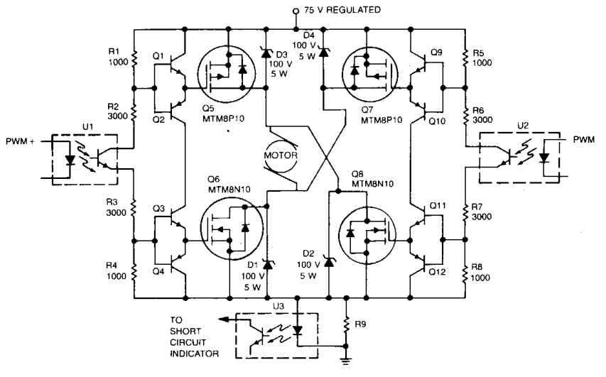
Digital integrated circuits (ICs) and opto-isolators supply the drive for this TMOS servo amplifier, leading to a reduction in analog circuits and minimizing drift. The fast and consistent turn-on and turn-off characteristics facilitate accurate analog output results directly from...
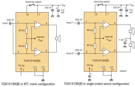
The audio amplifier circuit is based on the TDA1519 amplifier IC, which is designed for audio applications. The TDA1519 has a power output range of 2 to 6 watts. This amplifier is a Class B dual-output type and comes...
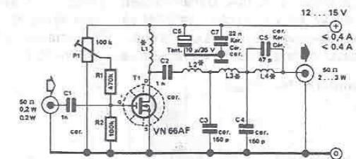
By using this RF amplifier, small power transmitters of 200 mW can be upgraded to reasonable power transmitters, ranging between 2 and 3 W. The circuit is straightforward. The output filter network suppresses noise by at least 55 dB....
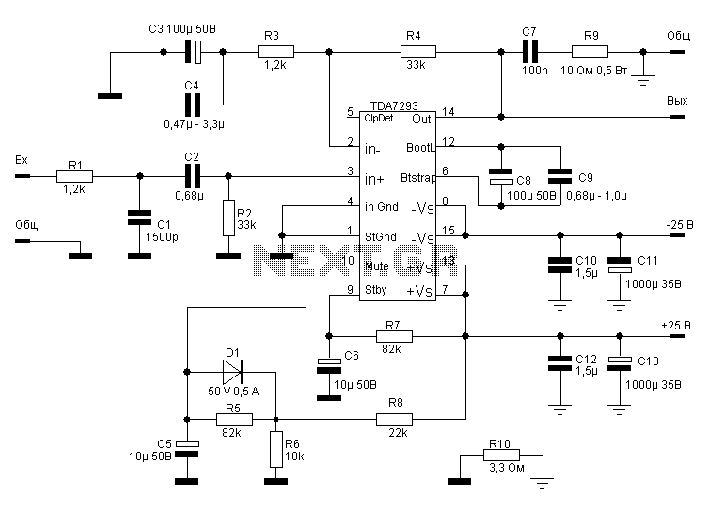
The TDA7293, produced by the ST (SGS-THOMSON) company, is a high-power, high-voltage DMOS high-fidelity amplifier integrated circuit (IC) with a rated output power of 100W. It operates at a maximum voltage of 120V. The key specifications include a dual...
JFET iPod preamplifier, DIY Hi-Fi, schematic The JFET iPod preamplifier circuit is designed to amplify the audio signal from an iPod or similar portable audio device, enabling it to drive higher impedance loads such as amplifiers or speakers. This circuit...