
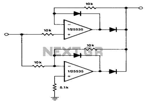
ULTRA PURE 125KHz SINE WAVE SIGNAL SOURCE

The ultra pure 125 kHz sine wave signal source is designed to meet the stringent requirements of RFID systems that operate at this frequency. The circuit utilizes precision components to ensure minimal distortion, which is critical for reliable communication in RFID applications. The output of the circuit is a 10-volt peak-to-peak sine wave, suitable for driving various RFID transponders and readers.
The circuit typically includes a waveform generator, which can be based on a precision oscillator or a microcontroller with a digital-to-analog converter (DAC). The oscillator is configured to generate a 125 kHz sine wave, and additional filtering stages may be employed to smooth the waveform and eliminate unwanted harmonics.
To achieve the desired output voltage, the circuit may incorporate an amplifier stage. This amplifier is designed to maintain linearity and low distortion while providing the necessary gain to achieve the 10-volt peak-to-peak output. Feedback mechanisms can be implemented to further enhance the stability and fidelity of the output signal.
Power supply considerations are also crucial, as the circuit must operate reliably under varying load conditions. A regulated power supply is often used to ensure that the oscillator and amplifier stages receive consistent voltage levels, thereby minimizing variations in signal output.
Overall, the design of the ultra pure 125 kHz sine wave signal source emphasizes precision, low distortion, and stability, making it an ideal choice for applications in RFID technology where signal integrity is paramount.ULTRA PURE 125KHz SINE WAVE SIGNAL SOURCE . For some RFID systems, which is at 125KHz, a very low distortion signal source is required. The circuit on this page results in a 10-volt peak-peak signal into. 🔗 External reference
Related Circuits
This circuit provides accurate full-wave rectification. The output impedance is low for both input polarities, and the errors are small at all signal levels. It is important to note that the output will not sink heavy currents, except for...
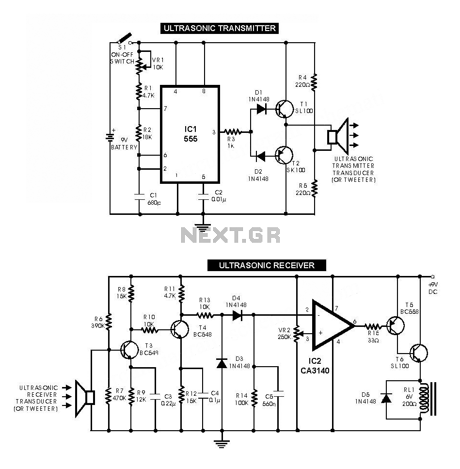
The ultrasonic sensor circuit comprises a transmitter and a receiver, which are essential for remote control applications. The circuit operates at sound frequencies above 20 kHz, typically between 40 kHz and 50 kHz, powered by a 9V battery. When...
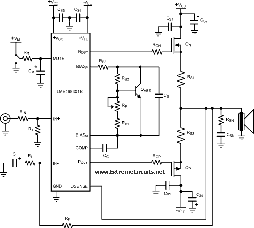
The LME49830 EF125WT1 amplifier PCB module features National Semiconductor's LME ultra-high fidelity power amplifier input stage integrated circuits (ICs) designed for driving applications. The LME49830 EF125WT1 amplifier PCB module is engineered to deliver exceptional audio performance, capitalizing on the advanced...
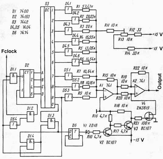
By utilizing a reverse binary counter along with a binary-coded decimal (BCD) decoder, a step voltage can be generated, which can then be approximated to produce a sine wave signal with adequate accuracy for various applications. In the digital...
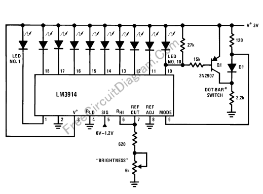
This LED (Light Emitting Diode) display consists of 10 LEDs to indicate the level of an input signal. If the signal is low, only LED #1 will light up. As the signal level increases, the illuminated dot will progress...
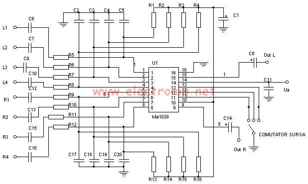
The TDA1029 is a dual operational amplifier configured as an impedance converter. Each amplifier features four mutually switchable inputs that are safeguarded by clamping diodes. Signal sources can be switched in various modes. The electronic components required for this...