
Ultra-simple Voltage Probe

This circuit functions as a simple voltage indicator with dual LED outputs to signify different conditions based on the type of voltage applied. It utilizes two light-emitting diodes (LEDs) – one red and one green – to provide visual feedback regarding the polarity of the voltage being measured and whether it is AC or DC.
The circuit is designed to operate with a DC voltage source. When the positive probe (typically colored red) is connected to the positive terminal of a DC source, the red LED will illuminate. This indicates a proper connection to a positive voltage. Conversely, if the probes are reversed, with the red probe connected to the negative terminal, the green LED will illuminate, indicating reverse polarity.
In the case of an AC voltage source, both LEDs will illuminate simultaneously. This feature allows for quick identification of AC voltage presence, as both LEDs do not light up under DC conditions unless the polarity is reversed.
A crucial component of this circuit is the inclusion of a current-limiting bulb that ensures the LEDs do not exceed their maximum current rating of 40mA, particularly when connected to high AC voltages, such as 220V. The bulb serves two purposes: it limits the current flowing through the LEDs and provides a visual indication of voltage presence. The filament of the bulb begins to glow at approximately 30V AC, becoming brighter as the voltage increases. This characteristic can be useful for applications requiring a visual confirmation of voltage levels.
The circuit's simplicity and low cost make it an attractive option for electrical testing and educational purposes, allowing users to easily identify voltage types and conditions without the need for complex instrumentation.This circuit is not a novelty, but it proved so useful, simple and cheap that it is worth building. When the positive (Red) probe is connected to a DC positive voltage and the Black probe to the negative, the Red LED will illuminate. Reversing polarities the Green LED will illuminate. Connecting the probes to an AC source both LEDs will go on. The bulb limits the LEDs current to 40mA @ 220V AC and its filament starts illuminating from about 30V, shining more brightly as voltage increases.
🔗 External reference
Related Circuits
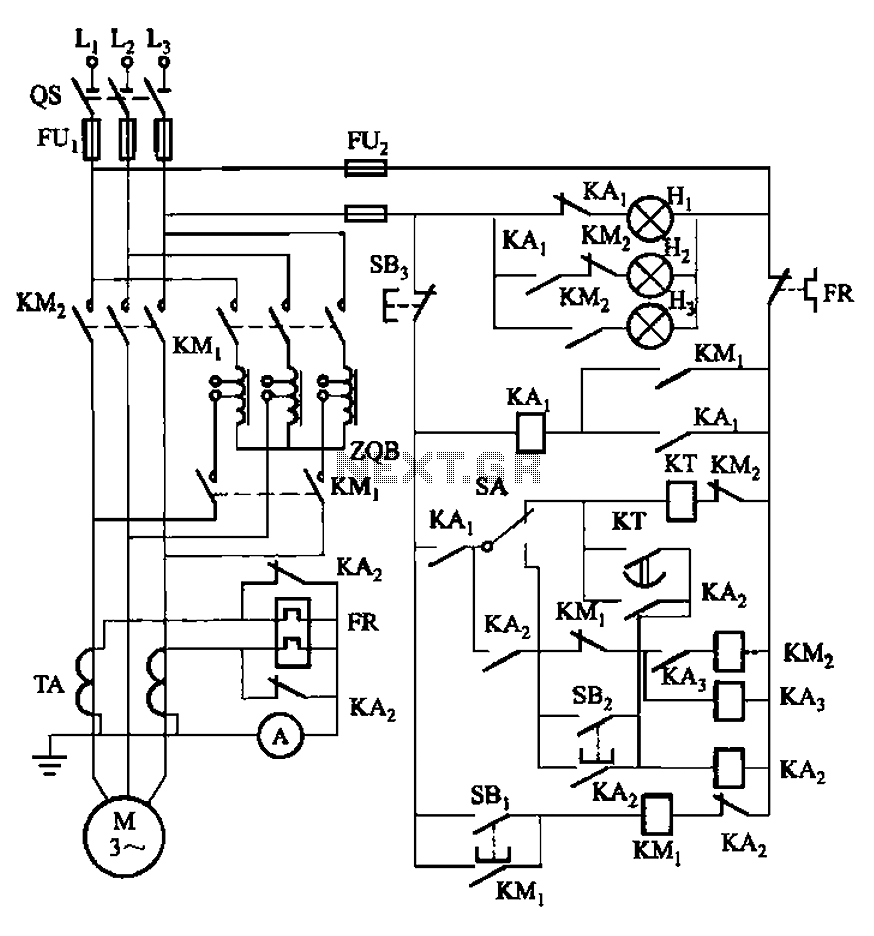
The circuit illustrated in Figure 3-56 features both manual and automatic start-up modes. It incorporates two relays, KA2 and KA3, within the control loop. The circuit design ensures that KM1 is cut off before and after activating KM2. A...

Field bus technology and intelligent instrument technology are currently two of the most rapidly evolving technologies in automation and control. In the realm of field bus technology, the CAN bus has established itself as a relatively fast communication standard...

The TRF1115 is the first of two ASICs utilized in the receiver section of the Texas Instruments MMDS/MDS/WCS/802.16x chipset. This device is responsible for down-converting the input frequency to an intermediate frequency (IF) within the range of 420 MHz...
This simple circuit tests speakers, microphones, transformers, and voltage. It is essentially a very low-frequency oscillator that generates extremely short, distinctive pulses. The sound produced is easy to hear and allows for precise localization, making it ideal for checking...

The schematic diagram originates from a 12V DC voltage doubler circuit power supply. This circuit diagram illustrates a DC voltage doubler/DC converter that transforms a 12V DC power supply into 24V DC and 18V DC outputs. It is compatible...

Undervoltage release operates over an extended period. When the power supply voltage drops within the operating voltage range, it triggers the release mechanism, resulting in the rotation of the tripping axle and the disconnection of the circuit breaker. There...