
Ultrasonic drilling machine circuit diagram 2

The ultrasonic drilling machine operates by utilizing high-frequency sound waves to facilitate drilling processes. The power supply circuit provides the necessary voltage and current to the entire system, ensuring stable operation. This circuit typically includes voltage regulators and filtering components to maintain a consistent output.
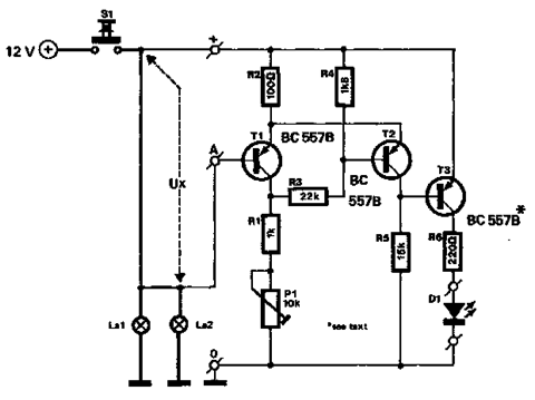
The ultrasonic oscillator circuit is the heart of the system, generating the high-frequency signals required for ultrasonic drilling. It employs a combination of resistors (R1 to R4), which determine the frequency and amplitude of the oscillations, and a transistor (V1) that acts as a switch to control the flow of current. Capacitors (C1 to C4) are used for tuning and stability, while the inductor (L) helps in shaping the oscillation waveform.
Following the oscillator, the preamplifier circuit boosts the weak signals produced by the ultrasonic oscillator. This stage is critical for ensuring that the signals are strong enough for further amplification. The promoting amplifier circuit then takes these signals and amplifies them further, preparing them for the final power amplification stage.
The power amplifier output circuit is responsible for driving the ultrasonic transducer, which converts electrical signals into mechanical vibrations. This stage must be designed to handle high power levels while maintaining efficiency and stability. Overall, each component in the ultrasonic drilling machine circuit plays a vital role in ensuring the effective generation and application of ultrasonic energy for drilling applications.The ultrasonic drilling machine circuit is composed of power supply circuit, ultrasonic oscillator circuit, preamplifier, promoting amplifier circuit and power amplifier output circuit, and the circuit is shown as the chart. Ultrasonic oscillator circuit consists of resistors R1 ~ R4, transistor V1, capacitors C1 ~ C4 and inductor L.
Preamplifier circuit con.. 🔗 External reference
Related Circuits
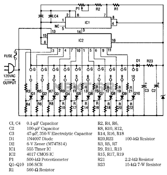
The light sequencer employs two integrated circuits (ICs) and ten silicon-controlled rectifiers (SCRs) to create an alternating current (AC) sequencer. The first IC, a 555 timer, is configured as an astable multivibrator to generate clock pulses for the second...
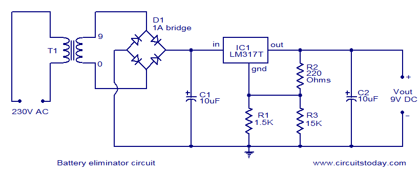
This document presents a circuit diagram of a battery eliminator circuit designed to replace 9V PP3 batteries. It can power any device that operates on a 9V battery. The transformer T1 reduces the mains voltage, while bridge rectifier D1...
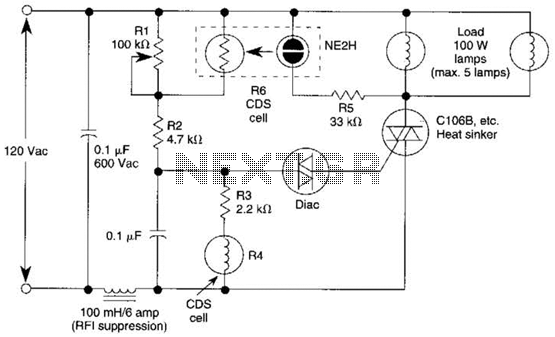
A neon bulb and a CdS photocell are enclosed in a light-tight enclosure to form an optocoupler. A diac/triac combination is employed to create a snap-switch effect. A second CdS photocell serves as the primary sensor. As darkness approaches,...
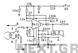
BA313 is a built-in automatic level control (ALC) circuit for audio recording preamplifiers, commonly used in cassette tape recorders. It is housed in a 9-pin dual in-line package (DIP) and features a wide range of automatic level control, operates...
The circuit described below monitors the car's brake lights and indicates their operational status using a 12V light-emitting diode (LED). This functionality can prevent fines for driving with defective brake lights and enhance road safety. The monitor relies on...
This house FM transmitter for your stereo or any other amplifier provides a strong signal strength up to a distance of 500 meters with a power output of about. This FM transmitter is designed to enhance audio transmission capabilities for...