
Ultrasonic Drilling Machine Two

The power supply section begins with the power switch (S1), which controls the flow of electricity to the circuit. Following the switch, the fuse (FU) provides protection against overcurrent conditions, ensuring that the circuit components remain safe from damage. The power transformer (T1) steps down the AC voltage to a suitable level for the circuit's operation.
The bridge rectifier, consisting of diodes (UR1 and UR2), converts the AC voltage from the transformer into a pulsating DC voltage. This DC voltage is then smoothed by the capacitors (C9 and C11-C13), which filter out the ripples, providing a stable DC supply to the subsequent stages of the circuit.
The ultrasonic oscillator circuit generates high-frequency signals necessary for ultrasonic applications. This signal is first amplified by the pre-amplifier, which boosts the weak signals from the oscillator. The amplifier further increases the signal strength before it reaches the power amplifier, which drives the output circuit. The power amplifier ensures that the output signal is strong enough to drive the load, which may be an ultrasonic transducer or another device requiring high-frequency signals.
Resistors (R16 and R17) are used within the circuit for biasing and setting gain levels in the amplifier stages, contributing to the overall performance and stability of the circuit. Each component plays a critical role in ensuring that the circuit functions effectively for its intended application, which may include ultrasonic cleaning, sensing, or other ultrasonic technologies.Work of the circuit The circuit consists of power supply circuit, ultrasonic oscillator circuit, pre-amplifier, amplifier and power amplifier drive output circuit. (It is showed in picture 8-125.)Power supply circuit consists of power switch Sl, fuse FU, power transformer m, bridge rectifier, URl and UR2, capacitors C9 and Cll-C13, resistors R16 and R17, v..
🔗 External reference
Related Circuits

Both converters utilize CMOS inverters. Figure 105-1A illustrates a free-running circuit where both pulse duration and pulse pause are influenced by the temperature of diode D8. This configuration is suitable for applications where synchronization between the converter and other...
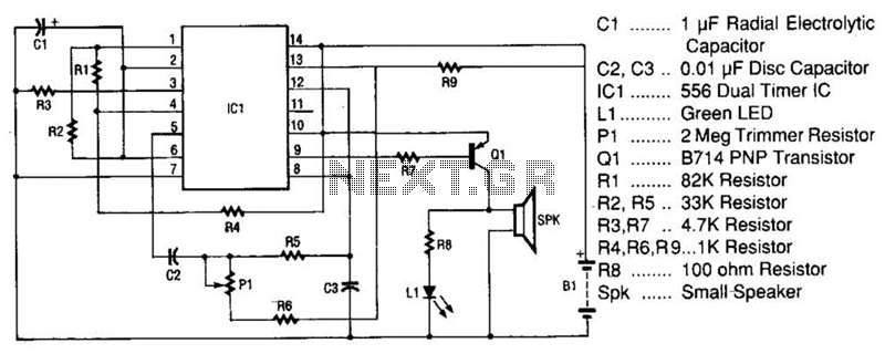
The space-age sound device utilizes a 556 dual timer integrated circuit (IC) to generate a phasor sound. This IC consists of two 555 timer circuits within a single 14-pin package, as depicted in the schematic. Each timer operates in...
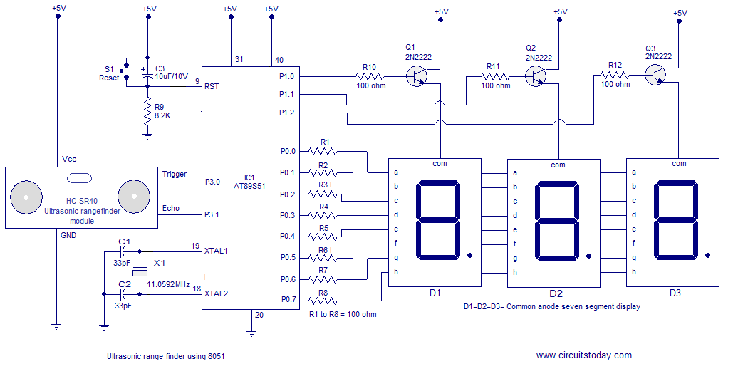
A simple ultrasonic range finder using the 8051 microcontroller is presented in this article. This ultrasonic rangefinder can measure distances up to 2.5 meters with an accuracy of 1 centimeter. The AT89S51 microcontroller and the ultrasonic transducer module HC-SR04...
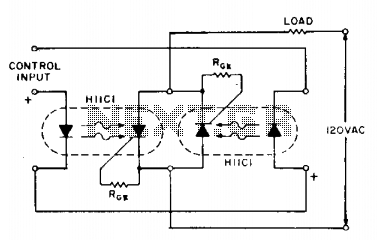
If load current requirements are relatively low (i.e., maximum forward RMS current of 500 mA), an AC solid-state relay can be constructed quite simply by connecting two H11C optically coupled SCRs in a back-to-back configuration as illustrated. The proposed circuit...

This project presents numerous practical applications in security and alarm systems for homes, shops, and vehicles. The circuit is highly sensitive and can be configured to either reset automatically or remain triggered until manually reset after an alarm. It...
The technology of range finding is extensively employed in civil and industrial fields, such as measurement, medical flaw detection, and car anti-collision systems, due to the relatively lower speed of ultrasonic waves compared to the speed of light. This...