
ultrasonic mosquito repeller

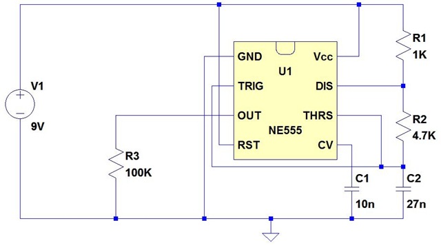
The ultrasonic mosquito repeller circuit leverages the characteristics of sound waves to deter mosquitoes effectively. The core component, the CMOS 4047 PLL IC, is versatile and well-suited for generating stable frequencies. In this application, it is configured in astable mode to produce a continuous square wave output at 22 kHz, which falls within the ultrasonic frequency range.
The output from the CMOS 4047 is relatively low in amplitude, necessitating amplification to ensure that the sound waves can effectively propagate through the environment. The complementary symmetry amplifier, which consists of four transistors arranged in a push-pull configuration, is employed to amplify the signal. This arrangement allows for efficient power usage and improved linearity in the amplification process, ensuring that the output maintains the integrity of the original signal while increasing its amplitude.
Following amplification, the signal is fed into a piezoelectric buzzer. The piezo buzzer is specifically designed to convert electrical energy into mechanical vibrations, producing sound waves. In this application, the buzzer is capable of generating ultrasonic frequencies that are inaudible to humans but can be perceived by mosquitoes. This targeted approach exploits the sensitivity of mosquitoes to specific sound frequencies, which can disrupt their mating behaviors and feeding patterns, effectively reducing their presence in the vicinity.
In summary, the ultrasonic mosquito repeller circuit is an effective solution for insect deterrence, utilizing a combination of a PLL oscillator, a complementary symmetry amplifier, and a piezo buzzer to generate ultrasonic frequencies that repel mosquitoes. The design emphasizes efficiency and functionality, making it a practical choice for pest control applications.Here is the circuit diagram of an ultrasonic mosquito repeller. The circuit is based on the theory that insects like mosquito can be repelled by using sound frequencies in the ultrasonic (above 20KHz) range. The circuit is nothing but a PLL IC CMOS 4047 wired as an oscillator working at 22KHz. A complementary symmetry amplifier consisting of four tra nsistor is used to amplify the sound. The piezo buzzer converts the output of amplifier to ultrasonic sound that can be heard by the insects. 🔗 External reference
Related Circuits
Circuit of a new type of remote control switch is described here. This circuit functions with inaudible (ultrasonic) sound. Sound of frequency up to 20 kHz is audible to human beings. The sound of frequency above 20 kHz is...
It is well known that many animals are particularly sensitive to high-frequency sounds that humans cannot hear. Many commercial pest repellers based on this principle are available, most of them operating in the range of 30 to 50 kHz....
The Panasonic transducers are no longer available, but the design remains interesting as an example. J1 connects to the RCX. D1 to D4 create a bridge rectifier to obtain local power from the RCX, which is stored on C7...
The issue began when a girlfriend expressed her frustration with mosquitoes disrupting her nights. It was recognized that mosquito sprays provide only temporary relief, as the insects tend to return after some time. A suggestion was made for an...
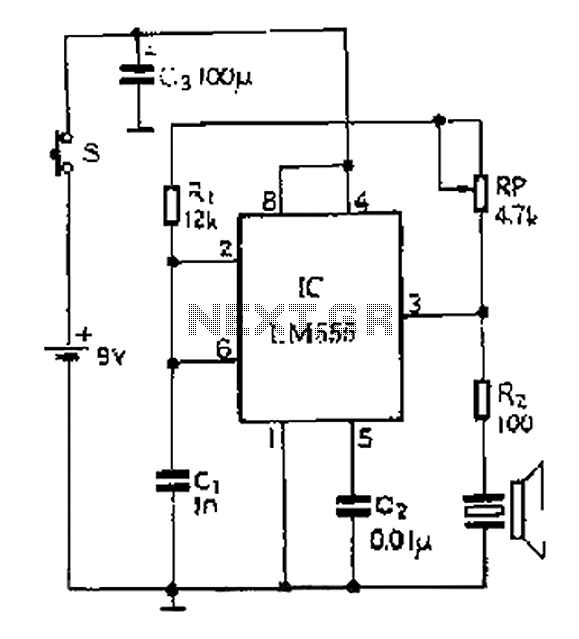
A 40 kHz ultrasonic transmitter circuit utilizes the LM555 timer as a time base circuit along with external components to create a 40 kHz multivibrator. The resistance of the adjustable resistor RP can modify the oscillation frequency. The output...
The T-40-16 and 555 ultrasonic transmitter circuit configuration consists of an ultrasonic transmitter T-40-16 and a 555 timer circuit. By adjusting the potentiometer RP, the oscillation frequency of the circuit can be changed. The output pulse frequency from the...