
Ultrasonic motion detector circuits

The motion sensor circuit is designed to detect movement and trigger a response based on the presence of motion in its vicinity. The circuit typically includes a motion sensor, such as a passive infrared (PIR) sensor, which detects changes in infrared radiation caused by moving objects, particularly warm bodies like humans or animals.
Upon applying a 12-volt power supply to the circuit, the PIR sensor begins to operate. It continuously monitors the environment for any infrared signals. When motion is detected, the sensor outputs a high signal, which can be used to activate other components in the circuit, such as a relay, LED, or alarm system.
The circuit may include additional components such as resistors and capacitors to filter signals and stabilize the operation of the motion sensor. A microcontroller or a comparator may also be integrated to process the sensor output and manage the response of the circuit, allowing for more advanced features such as adjustable sensitivity or delay times.
Connections in the circuit must be made properly to ensure that the sensor receives the correct voltage and that the output is directed to the intended device. The layout should minimize interference from external sources, and careful consideration should be given to the placement of the PIR sensor to maximize its detection range.
Overall, this motion sensor circuit is a versatile solution for various applications, including security systems, automatic lighting, and energy-saving devices, providing a reliable means of detecting movement and responding accordingly.From circuits in Figure 1 is the motion sensor circuit. The working of circuit to start from when we apply a power supply 12 volt to input point 12 volt. T From circuits in Figure 1 is the motion sensor circuit. The working of circuit to start from when we apply a power supply 12 volt to input point 12 volt. Then.. 🔗 External reference
Related Circuits
In audio systems, noise signals are generally undesirable, and efforts are often made to eliminate them. Transistors can be utilized effectively for this purpose due to their availability and low noise characteristics. The following circuit serves as a Noise...
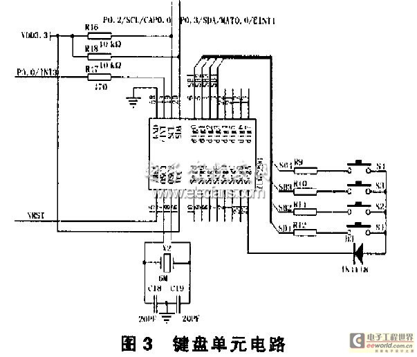
The gas detector designed in this instance utilizes an ARM microprocessor as its core for measurement and control. It not only incorporates advanced one-chip computer microprocessing technology from the 1990s but also features several enhancements. The device employs an...
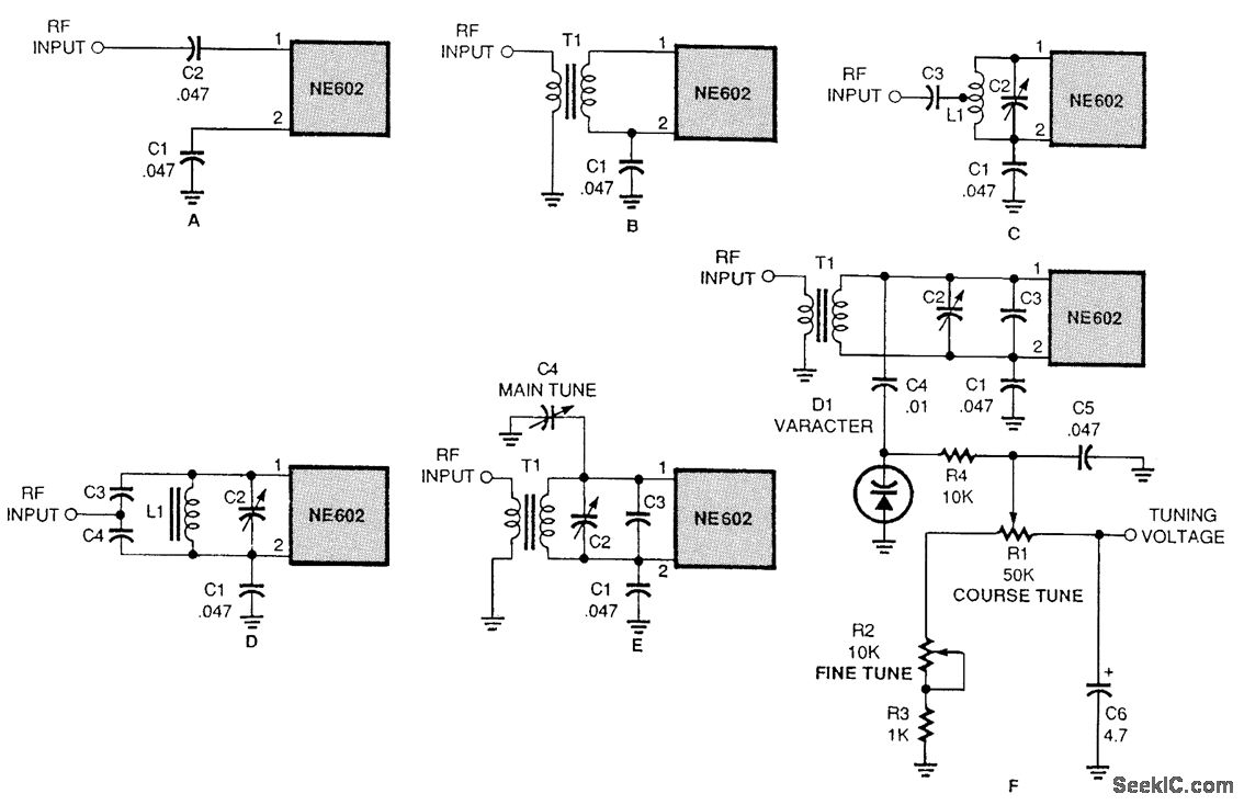
There are several methods to input a signal into the NE602. Simple untuned approaches (a and b) are viable. For tuning to a specific frequency, an LC resonant circuit with ungrounded trimmer capacitors (c and d) or grounded variable...
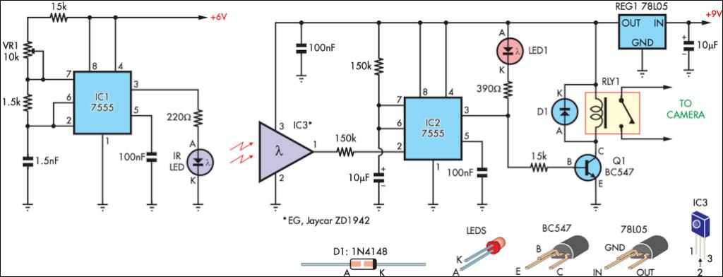
This circuit serves as an alternative to the infrared beam break detector discussed in the June 2009 issue of Silicon Chip. It aims to provide a more efficient solution for detecting interruptions in an infrared beam. This alternative infrared beam...
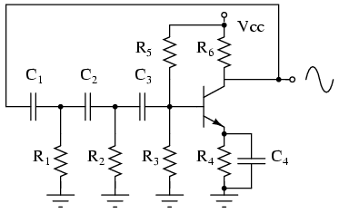
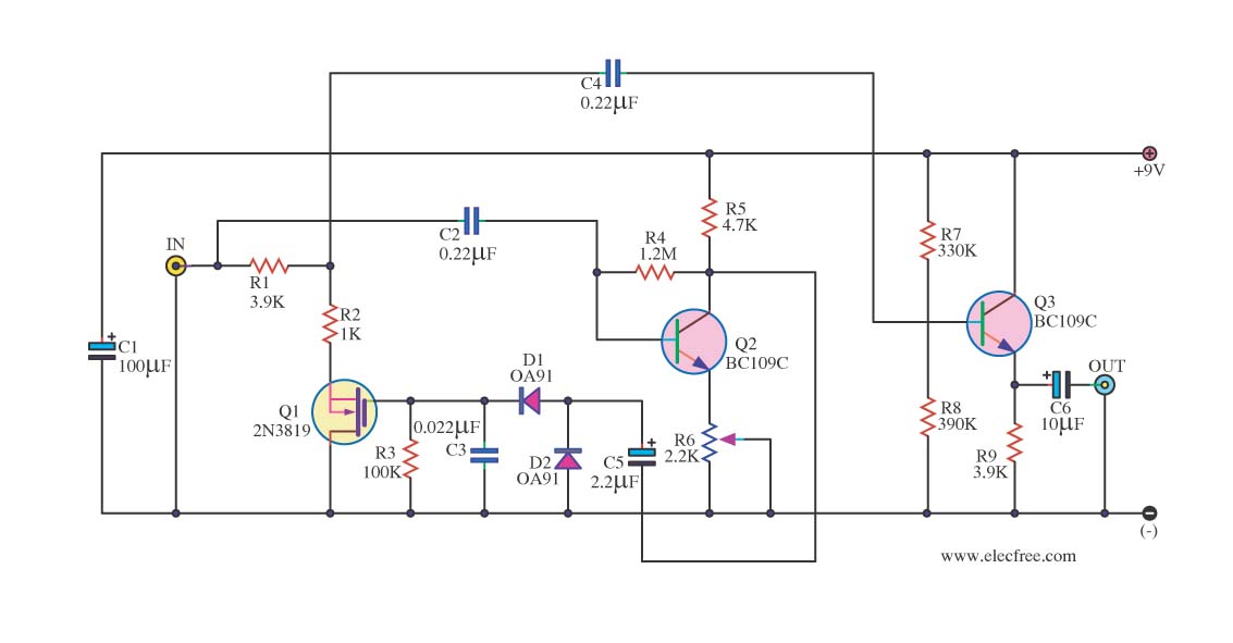
The phase shift oscillator produces a sine wave output in the audio frequency range. Resistive feedback from the collector results in negative feedback due to a 180-degree phase inversion from the base to the collector. The three 60-degree RC...
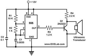
The ultrasonic cleaning machine functions as a humidifier and operates on a simple circuit primarily consisting of an ultrasonic oscillator. It generates ultrasonic frequency signals, typically within the range of 20-40 kHz, using a transistor. These signals are transmitted...