
Ultrasonic-receiver

The piezo speaker, MIC1, detects the incoming ultrasonic signal and transmits it to the base of Q1. A two-transistor booster amplifier composed of Q1 and Q2 amplifies the signal to a level adequate for driving one input of this unique mixer circuit. Integrated circuit U2, a quad bilateral switch, operates as a highly efficient balanced mixer circuit for the superheterodyne receiver. Integrated circuit U1a, one section of a dual op-amp, is configured in a variable-frequency square-wave oscillator circuit. Resistors R5, R6, and capacitor C4 set the frequency and tuning range of the oscillator. The square-wave output of U1a is directed along two paths. One path sends the output to pins 12 and 13 of U2, while the other path feeds the signal to the base of Q3, which acts as an inverter. The inverter produces an output that is 180 degrees out of phase with the input signal. The inverted output from Q3 is then sent to U2 at pins 5 and 6. Here, the two input signals—the ultrasonic input from MIC1 and the oscillator output—are mixed. This mixing generates an audible product that is directed to the input of a differential amplifier, U1b, the second half of the dual op-amp, which provides a voltage gain of two. The output of U1b at pin 7 is processed through R19 and C9 to eliminate the high-frequency components of the mixed signal. The difference frequency is the primary focus, as the sum frequency, which is the combination of the incoming ultrasonic signal and the oscillator frequency, exceeds the hearing range of humans. R19 and C9 effectively remove the sum frequency, resulting in a clean output signal that feeds into power amplifier U3. Resistor R21 serves as the circuit's volume control.
The circuit described operates as a superheterodyne receiver, utilizing a piezo speaker as a sensor for ultrasonic signals. The initial signal captured by MIC1 is critical for detecting high-frequency inputs. The two-transistor amplifier, consisting of Q1 and Q2, is designed to enhance the signal strength to ensure it meets the operational requirements of the subsequent mixer stage. The balanced mixer configuration in U2 allows for efficient mixing of the incoming ultrasonic signal with the square-wave output generated by the oscillator circuit formed by U1a.
The oscillator circuit plays a vital role in modulating the ultrasonic signal. The frequency of oscillation is determined by the values of resistors R5, R6, and capacitor C4, which can be adjusted to vary the operational frequency of the system. This flexibility is essential for tuning the receiver to specific ultrasonic frequencies, enhancing its functionality in various applications.
The inverter stage using Q3 is crucial for generating a signal that is out of phase, which is necessary for proper mixing in U2. The two distinct input signals—one being the ultrasonic signal from MIC1 and the other being the square wave from U1a—are mixed to produce an audible output. The differential amplifier U1b amplifies this mixed signal, ensuring that the desired difference frequency is emphasized while filtering out unwanted high-frequency components.
The filtering components R19 and C9 are strategically placed to remove the sum frequency, which is not perceptible to human hearing. This filtering allows for the extraction of the difference frequency, which is the target signal. The output is then routed to power amplifier U3, which amplifies the clean signal for further use, such as driving a speaker or other output device. The inclusion of resistor R21 as a volume control allows for user-adjustable output levels, enhancing the usability of the circuit in practical applications. Overall, this schematic represents a sophisticated approach to ultrasonic signal processing, integrating various components to achieve a functional and adaptable receiver system.The piezo speaker, MICl, picks up the incoming ultrasonic signal and feeds it to the base of Ql. The two-transistor booster amplifier, Ql and Q2, raises the signal to a level that is sufficient to drive one input of this most unusual mixer circuit. Integrated circuit U2, a quad bilateral switch, functions as an extremely clean balanced-mixe. circuit for the superheterodyne receiver. Integrated circuit U1a, lfz of a dual op amp, is connected in a~variablefrequency square-wave oscillator circuit. Resistors R5, R6, and capacitor C4 determine the frequency and tuning range of the oscillator. The oscillator"s square-wave output is fed along two paths. In one path, the output of Ula is input to pins 12 and 13 of U2. In the other path, the signal is fed to the base of Q3, which is configured as an inverter. The inverter outputs a signal that is 180° out-of-phase with the input signal. The inverted output of Q3 is then fed to U2 at pins 5 and 6. There, the two input signals, the ultrasonic input from MICl and the oscillator output, are mixed. The mixing of the ultrasonic input and the square-wave signal produces an audible product that is fed to the input of a differential amplifier, U1b, the second half of the dual op amp, which has a voltage gain of two.
The output of U1b at pin 7 is filtered by R19 and C9 to remove the highfrequency content ofthe mixed signal. Only the difference frequency is important; the sum frequency, the incoming ultrasonic signal added to the oscillator frequency, is too high for the human ear to hear.
The sum frequency is removed by R19 and C9 to produce a clean output signal to feed power-amplifier U3. Resistor R21 functions as the circuit"s volume control.
Related Circuits
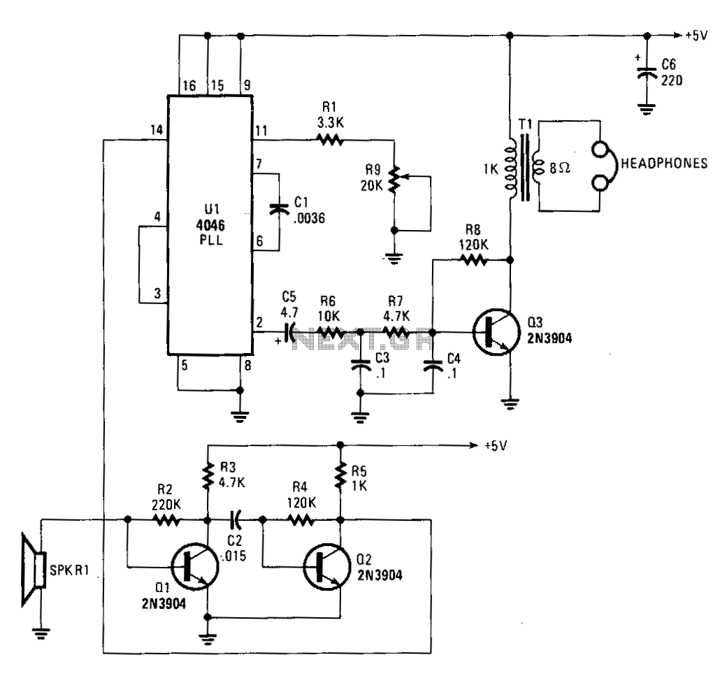
The 4046 PLL is utilized as the core component of a tunable ultrasonic receiver designed for detecting inaudible ultrasonic sounds. This receiver can also function in conjunction with a simple ultrasonic generator to transmit and receive Morse code. The...