
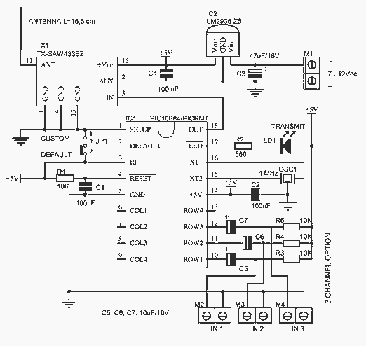
Ultrasonic Transmitter Sensor Switch circuit

The described circuit employs an ultrasonic sensor to facilitate wireless switching, allowing for the activation or deactivation of devices based on distance measurements. The ultrasonic sensor operates by emitting high-frequency sound waves and measuring the time taken for the echo to return after bouncing off an object. This time is then converted into a distance measurement, which is compared against a predetermined threshold to determine whether the switching action should occur.
For implementation, the circuit requires a microcontroller unit (MCU) to process the signals from the ultrasonic sensor. The MCU is programmed to continuously monitor the distance readings. When an object is detected within the specified range (greater than 10 meters in this case), the microcontroller triggers a wireless transmitter module, such as a radio frequency (RF) transmitter or a Wi-Fi module, to send a signal to a corresponding receiver module connected to the target device.
Power supply considerations are critical, as the circuit must operate effectively over the intended distance. A stable power source, such as batteries or a regulated power supply, should be used to ensure consistent operation of the ultrasonic sensor and the microcontroller. Additionally, the design may include features such as low-power modes to extend battery life during periods of inactivity.
A feedback mechanism could also be incorporated, allowing the system to confirm the successful execution of the switching action. This could involve the use of LEDs or other indicators to provide visual confirmation when a command has been successfully transmitted and received.
Overall, the circuit represents a versatile solution for wireless switching applications, leveraging ultrasonic sensing technology to achieve operational ranges exceeding 10 meters.This circuit explain about alternate wireless switching using ultrasonic sensor. The distance of switching range should be more than 10 meters .. 🔗 External reference
Related Circuits
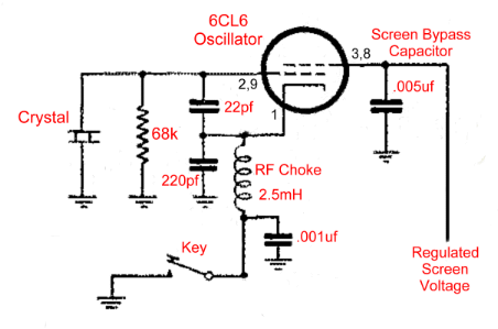
The operation of the 6CL6 transmitter is quite sophisticated despite the simple appearance of the circuit. The core of the circuit is the electron-coupled crystal oscillator. This circuit integrates the functions of an oscillator and amplifier into a single...
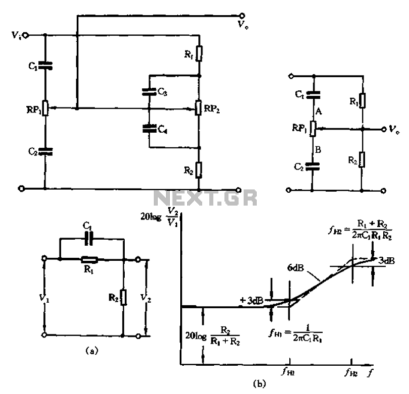
The circuit illustrated in Figure 1-560 represents a treble control potentiometer. Due to the larger capacitance values of C3 and C4 compared to C1 and C2, high-frequency signals can treat C4 as a short circuit. Consequently, the treble adjustment...
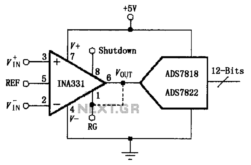
The INA331/332 is configured to directly drive a capacitive input A/D converter. Due to the low output resistance of the INA331/332, it is capable of operating at high frequencies and can directly handle capacitive loads. The output voltage from...
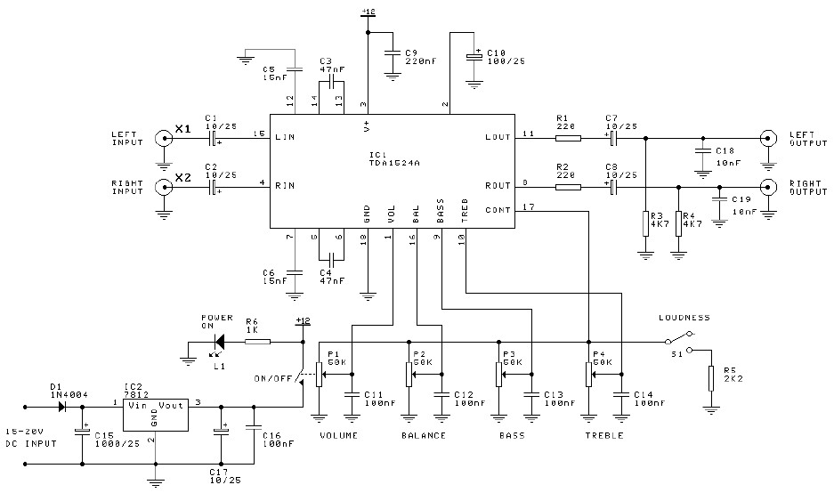
Preamplifier and tone control circuit based on the TDA1524A. The tone control circuit module is included in this preamplifier circuit, allowing for direct connection of the output channels to a stereo power audio amplifier circuit. This RIAA stereo preamplifier...
This circuit was formed to create a wireless alarm from a normal magnetic contact. By fixing the magnet to the leaf of a door, or swing of a drawer, it is easy to reveal the opening. To transmit the...
The video amplifier depicted in the diagram is a widely recognized design that is both simple and highly effective. However, the transistors are susceptible to damage if the potentiometers (black level and signal amplitude) are set to their extreme...