
Understanding the Music Man Stingray 2-band preamp

The Music Man Stingray bass guitar preamp circuit is designed to amplify the low-level signals generated by the guitar's pickups. The preamp typically consists of several key components, including operational amplifiers, resistors, capacitors, and a power supply input. The choice of a 9V DC power supply is common in many audio applications, providing a balance between adequate headroom and low noise.
At the input stage, the preamp circuit typically includes a high-impedance buffer to ensure that the signal from the guitar pickups is not loaded down. This is often implemented using an operational amplifier configured as a non-inverting amplifier. The gain of this stage can be adjusted by selecting appropriate feedback and input resistors.
Following the input stage, additional filtering capacitors may be included to remove unwanted high-frequency noise and to stabilize the power supply. The circuit may also feature tone control elements, such as passive RC networks, allowing the user to adjust bass, midrange, and treble frequencies according to personal preference.
The output stage of the preamp is designed to drive the subsequent amplification stages or effects pedals. This stage may also utilize an operational amplifier to ensure that the output signal maintains a low output impedance, facilitating better signal transfer to the next stage in the audio chain.
In summary, the schematic for the Music Man Stingray bass guitar preamp illustrates a well-thought-out design that emphasizes signal integrity, user control over tonal characteristics, and compatibility with standard audio equipment. The omission of the voltage divider section suggests a focus on simplifying the schematic for clarity, while still retaining the essential functionality of the preamp circuit.The schematic here is of the original Music Man Stingray bass guitar preamp. It runs off 9VDC and I have left off the voltage divider part of the.. 🔗 External reference
Related Circuits
Phonographs are becoming increasingly rare as they are being replaced by more advanced audio systems such as CD players, recorders, and portable MiniDisc player/recorders. This shift is acknowledged by audio equipment manufacturers, leading to the omission of traditional phono...
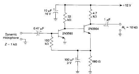
This microphone preamplifier electronic project is based on transistors and is capable of approximately 70 dB or more gain at audio frequencies. The gain of this circuit is roughly equal to the product of the hfe (current gain) of...
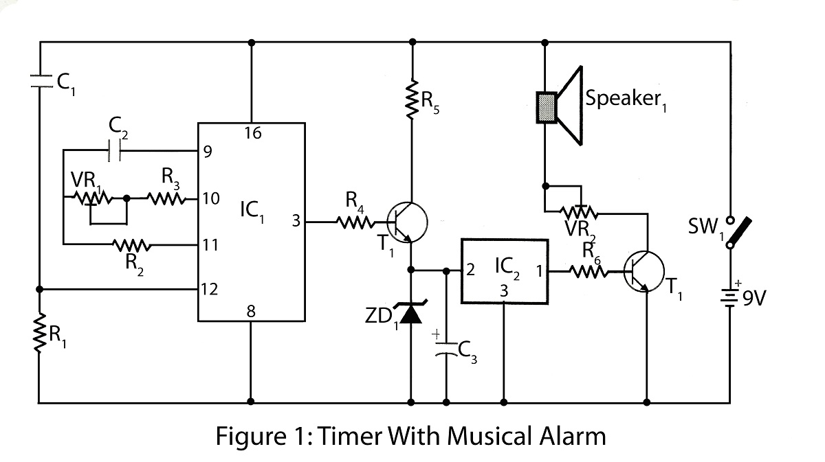
The timer with a musical alarm is an electronic timer project utilizing the CD4060 integrated circuit. It provides a delay ranging from 1 minute to 2 hours. The circuit diagram for the timer with a musical alarm is part...
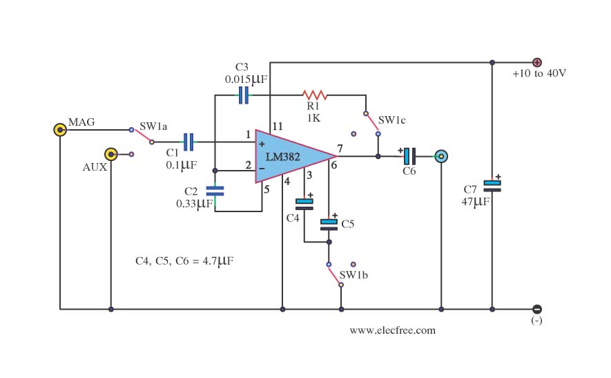
This is a simple preamplifier circuit. It can accept a general AUX sound signal as well as a signal from a microphone. The purpose of the circuit is to amplify the sound signal at the initial stage using an...
This preamplifier is designed for low-resistance sources such as moving coil heads (MC). The circuit employs three parallel double transistors, SSM2220 or MAT03, which form a differential amplifier that minimizes noise. When connected to an OP27 amplifier, it further...
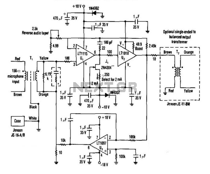
A low-noise LT1115 (Linear Technology, Inc.) operational amplifier is connected to a class-A buffer amplifier to create a variable gain (12-to-50 dB) microphone preamplifier. Total harmonic distortion (THD) is less than 0.01% across a frequency range from 80 Hz...