
uninterruptible power supply

The 220 watts Uninterruptible Power Supply (UPS) is designed to provide reliable backup power during outages, ensuring that connected devices remain operational. The UPS typically includes a battery, inverter, and various control circuits. The battery stores energy, while the inverter converts the direct current (DC) from the battery into alternating current (AC), which is used by most electronic devices.
The circuit diagram of the UPS includes several key components. The battery management system monitors the state of the battery, ensuring it is charged properly and preventing over-discharge. A charging circuit, often utilizing a transformer and rectifier, converts AC mains power to DC for charging the battery.
The inverter section is critical to the UPS operation. It usually employs a combination of power transistors or MOSFETs configured in a push-pull or half-bridge arrangement to generate the required AC output. The control circuit regulates the output voltage and frequency, ensuring that the output remains stable under varying load conditions.
Additional features may include surge protection, overload protection, and indicators for battery status and load level. These components work together to create a robust power supply solution capable of supporting sensitive electronic equipment during power interruptions.
The overall design prioritizes efficiency and reliability, making it suitable for applications such as home offices, medical equipment, and data centers where continuous power is essential.220 watts Uninterruptible Power Supply power supply. Go to that page to read the explanation about above power supply related circuit diagram. 🔗 External reference
Related Circuits

Cable and xDSL modems are increasingly popular, leading to a need for designs that interface with existing telephones at subscriber locations. The subscriber line interface circuit (SLIC) within the modem must ring the phone and provide loop current during...
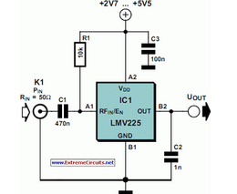
The National Semiconductor LMV225 is a linear RF power meter integrated circuit (IC) in a surface-mount device (SMD) package. It operates over a frequency range of 450 MHz to 2000 MHz. The LMV225 is designed for precise measurement of radio...
This power supply is designed as either an auxiliary or a permanent power source for various circuits that require a stabilized DC voltage ranging from 3 to 30V, with a maximum current consumption of 3A. Additionally, this power supply...
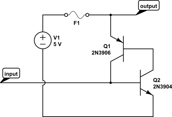
The circuit should default to the "on" state when first connected. However, if a specific signal goes high for a brief duration (approximately 10 microseconds), the circuit should turn off and remain off. The challenge lies in achieving the...
The micropower circuit automatically provides shutdown, power-up, and low-battery lockout functions without requiring software or operator control. The micropower circuit is designed to manage power efficiently in battery-operated devices, ensuring optimal functionality while conserving energy. The shutdown feature is activated...
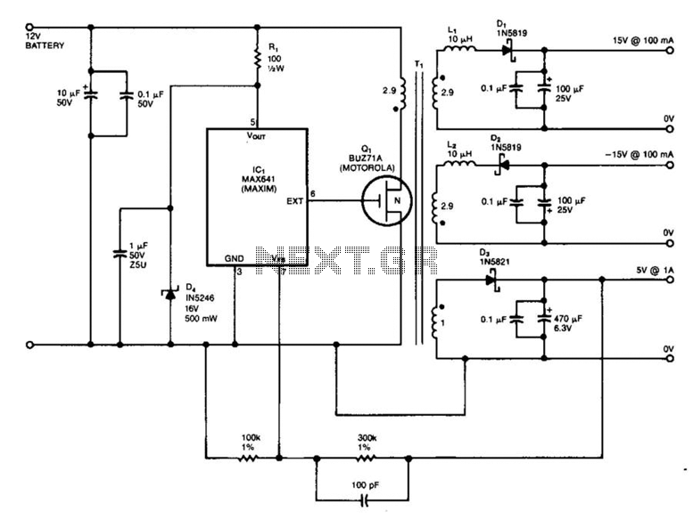
IC1 is a switching regulator that generates a 45-kHz signal to drive the gate of MOSFET Q1. Diodes D1, D2, and D3 are Schottky diodes. The 5-V output is monitored as a reference; feedback to the chip disables the...